Optical cable spreading burying machine

A technology for optical cables and cables, which is applied in the field of optical cable laying and embedding machines, can solve problems such as complex structure of optical cable embedding machines, inability to achieve synchronization, and affect laying quality, and achieve the effects of optimizing cutting effects, improving efficiency, and optimizing excavation efficiency

Inactive Publication Date: 2015-05-20
INNER MONGOLIA XIANGYU COMM NETWORK ENG
View PDF9 Cites 0 Cited by
  • Summary
  • Abstract
  • Description
  • Claims
  • Application Information

AI Technical Summary

Problems solved by technology

[0005] Therefore, the technical problem to be solved by the present invention is that the structure of the optical cable laying machine in the prior art is complicated, and the walking, slotting, and wire feeding cannot be synchronized, thereby affecting the laying quality, and then providing a power that can be reasonably distributed. , optical cable laying and embedding machine that walks, slots, and feeds synchronously

Method used


Image

  • Optical cable spreading burying machine
  • Optical cable spreading burying machine
  • Optical cable spreading burying machine

Examples


Embodiment Construction

[0054] In the following, the present invention will be further described by using the following embodiments in conjunction with the accompanying drawings.

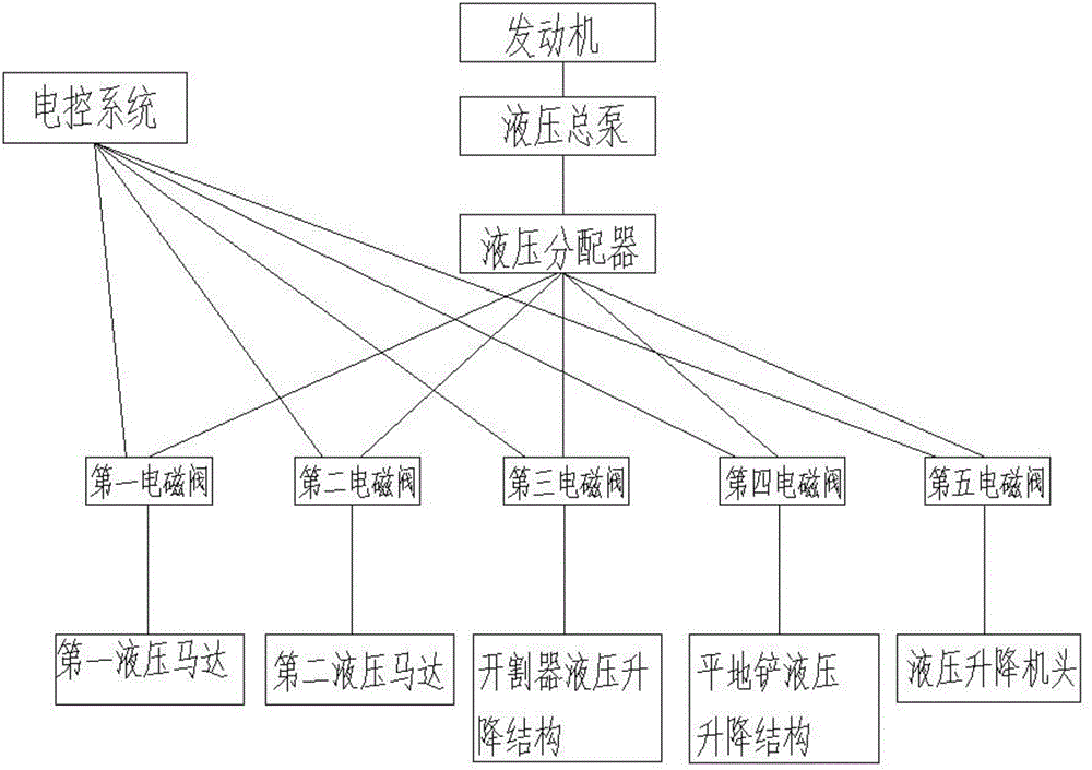
[0055] Such as figure 1 , 2 As shown, an optical cable embedding machine in this embodiment includes a trolley A1, a slotting device, a wire feeding device, an optical cable grounding device C4, and a soil covering device A2, wherein the slotting device includes a disc cutter A3, the traveling vehicle A1 is provided with a first hydraulic motor A10 for driving the traveling wheels or the traveling crawler;

[0056] The slotting device is provided with a second hydraulic motor A11 that drives the disc cutter A3 to rotate;

[0057] It also includes a power distribution device, the power distribution device includes a hydraulic master cylinder driven by the engine of the traveling vehicle A1, and distributes the high-pressure hydraulic oil of the hydraulic master cylinder to the first hydraulic motor A10, the second The hy...


PUM


Abstract

The invention discloses an optical cable spreading burying machine which comprises a travelling vehicle, a grooving device, a cable feeding device, an optical cable underground device and an earth covering device. The grooving device comprises a disc cutting device, a first hydraulic motor which drives travelling wheels or travelling crawler belts to travel is arranged on the traveling vehicle, and a second hydraulic motor which drives the disc cutting device to rotate is arranged on the grooving device. The optical cable spreading burying machine further comprises a power distribution device, the power distribution device comprises a hydraulic master pump driven by the motor of the traveling vehicle, high-pressure hydraulic of the hydraulic master pump is distributed to a hydraulic distributor of the first hydraulic motor, a hydraulic distributor of the second hydraulic motor, a first electromagnetic valve and a second electromagnetic valve, the first electromagnetic valve is arranged between the hydraulic distributor of the first hydraulic motor and the first hydraulic motor and controls the operation of the travelling wheels and the travelling crawler belts, and the second electromagnetic valve is arranged between the hydraulic distributor of the second hydraulic motor and the second hydraulic motor and controls the rotation direction of the disc cutting device. The optical cable spreading burying machine is purely controlled by hydraulic pressure, is compact and simple in structure, can travel and groove synchronously, and can achieve composite force distribution of power of the parts.

Description

technical field [0001] The invention relates to an optical cable laying and embedding machine, in particular to an optical cable laying and embedding machine with full hydraulic control and synchronous walking and laying. Background technique [0002] The laying of communication lines is an important part of information infrastructure construction. The speed and quality of line laying determine the progress of information infrastructure construction and whether the people can obtain information resources safely, quickly and stably. It is a measure of the degree of informatization of a country. Always be standard. [0003] At present, the methods of laying optical cables in my country mainly include direct buried optical cables, aerial laying optical cables and submarine laying optical cable tubes. Considering the convenience of construction, maintenance, use and construction costs, long-distance optical cables are generally laid by direct burial. In urban buildings, overhea...

Claims


Application Information

Patent Timeline
Patent Type & Authority Patents(China)
IPC IPC(8): E02F5/10G02B6/54
Inventor 郭志忠
Owner INNER MONGOLIA XIANGYU COMM NETWORK ENG
Why Eureka
Try Eureka