Supercharge Your Innovation With Domain-Expert AI Agents!

Intelligent wireless detecting system for longitudinal tearing of conveying belts

A technology of longitudinal tearing and intelligent detection, applied in the direction of conveyor objects, conveyor control devices, transportation and packaging, etc., can solve problems such as difficult to ensure timely detection of tearing, production troubles, cable laying, maintenance difficulties, etc., to achieve Simple longitudinal tear wireless intelligent detection scheme, quick response, solve the effect of untimely tear fault detection

Active Publication Date: 2013-06-12
JIANGNAN UNIV
View PDF6 Cites 0 Cited by
  • Summary
  • Abstract
  • Description
  • Claims
  • Application Information

AI Technical Summary

Problems solved by technology

This conveyor belt longitudinal anti-tear detection system sets the embedded coil detector to detect the state of the coil under the most easily torn part of the conveyor belt. The disadvantage is that if the damaged coil starts at the farthest distance from the embedded coil If the coil is torn, it can only be detected when the coil moves with the belt to the top of the embedded coil detector. It is difficult to ensure that the tear is detected in time, which brings great trouble to production.
Its disadvantages are also that electrical equipment such as embedded coil detectors, mutual control computers, alarms, motor switches and other electrical equipment in this conveyor belt longitudinal anti-tear detection system can only be connected by cables, and it is difficult to lay cables and maintain them in some complex terrain areas. has considerable limitations

Method used


Image

  • Intelligent wireless detecting system for longitudinal tearing of conveying belts
  • Intelligent wireless detecting system for longitudinal tearing of conveying belts
  • Intelligent wireless detecting system for longitudinal tearing of conveying belts

Examples


Embodiment Construction

[0015] The present invention will be further described below in conjunction with drawings and embodiments.

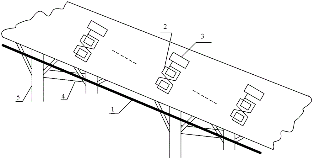
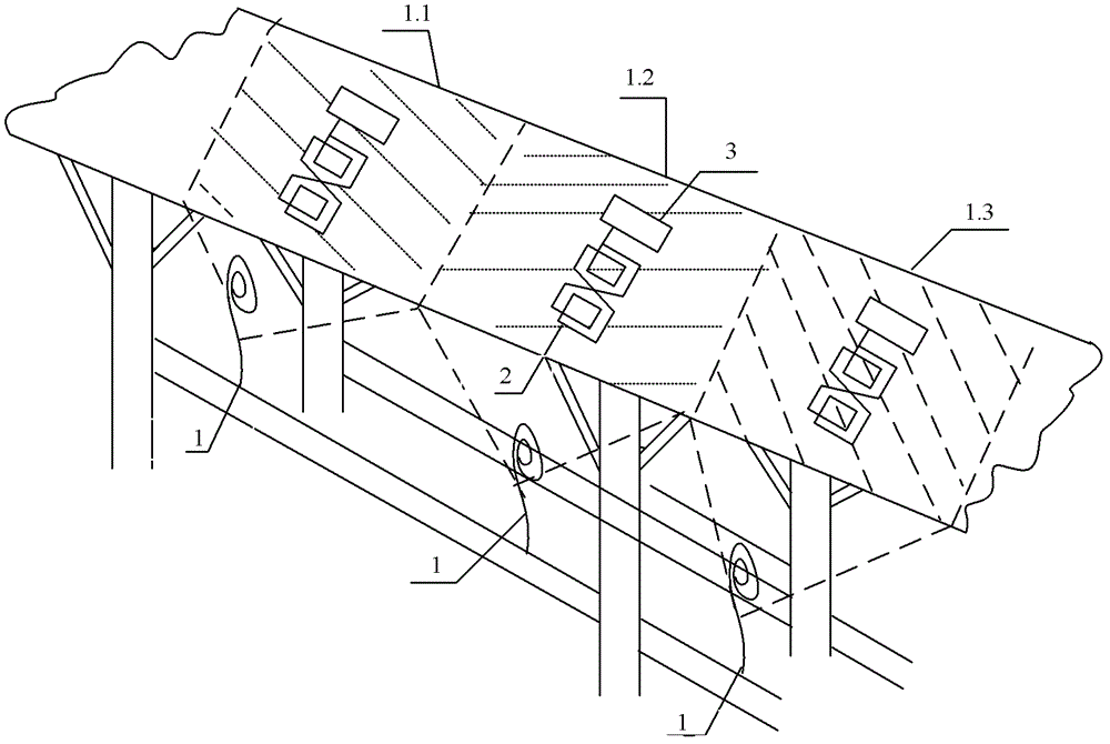
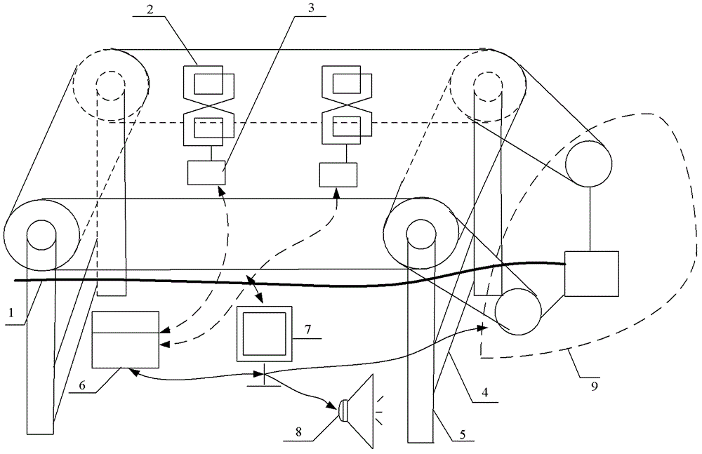
[0016] like figure 1 As shown, the present invention includes external antenna 1, multiple groups of internal antennas 2 and ZigBee modules 3 pre-embedded in the conveyor belt, the external antenna 1 is connected with the conveyor belt motor, laid along the conveyor belt, the power supply of each ZigBee module 3 One or a set of internal antennas 2 are connected to the terminal. The ZigBee module 3 pre-embedded in the conveyor belt has a film-shaped structure and good flexibility, and will not be damaged naturally due to folding. The internal storage module of the ZigBee module 3 is used to record the conveyor belt position number, production date, and conveyor belt accumulation. Effective information such as normal working time and damage time. When the conveyor belt motor is working normally, the external antenna 1 converts the transmitted electric energy into electr...


PUM


Abstract

The invention provides an intelligent wireless detecting system for longitudinal tearing of conveying belts, which comprises an external antenna, a plurality of internal antenna sets and ZigBee modules, wherein the internal antennas are embedded into a conveying belt. The external antenna is connected with a conveying belt motor and laid along the conveying belt, and a power end of each ZigBee module is connected with one internal antenna or one internal antenna set. When a conveying belt motor is operated normally, the external antenna converts transmitted electric energy into electromagnetic energy and continuously sends out electromagnetic signals of specific frequency, and the internal antennas converts the electromagnetic signals transmitted by the external antenna into electric signals to provide power voltage for the ZigBee modules. Conveying belt information including conveying belt position numbers is stored and transmitted to a superior control center by the ZigBee modules. The intelligent wireless detecting system has the advantages of quickness in response, accuracy in positioning, high interference resistance, high efficiency, stability and capability of effectively solving the problems that tearing fault detection in the prior art is untimely, equipment connecting cables are difficult in laying and maintenance, and the like.

Description

technical field [0001] The invention relates to a wireless detection system, in particular to a wireless intelligent detection system for detecting longitudinal tearing of conveyor belts. Background technique [0002] Modern belt conveyors have a large transportation volume, long transportation distance, fast speed, high efficiency, and multiple functions. They are widely used in large-scale material transportation in industrial and mining plants, steel factories, wharfs, etc., and are the core tool for material transportation. In the above-mentioned transportation environment, the conveyor belt is prone to longitudinal tearing accidents during the conveying process caused by material entrapment and scratches by sharp foreign objects. If it is not found and repaired in time, the tear in the belt body will spread rapidly, causing the conveyor to be forced to stop , Stop production, causing huge economic losses and potential safety hazards to the enterprise. Therefore, how to...

Claims


Application Information

Patent Timeline
Patent Type & Authority Patents(China)
IPC IPC(8): B65G43/06
Inventor 高春能王聪纪志成王艳
Owner JIANGNAN UNIV
Features
  • R&D
  • Intellectual Property
  • Life Sciences
  • Materials
  • Tech Scout
  • Unparalleled Data Quality
  • Higher Quality Content
  • 60% Fewer Hallucinations
Learn More