Eureka AIR delivers breakthrough ideas for toughest innovation challenges, trusted by R&D personnel around the world.

High-temperature high-pressure dyejigger

A high-temperature, high-pressure, jigger technology, which is applied to textile processing machine accessories, textiles and papermaking, and textile material processing, can solve problems such as time-consuming and labor-intensive, uneven pressure and heat, and horizontal sliding of fabrics to ensure dyeing quality. , easy to operate and use, high work efficiency

Inactive Publication Date: 2012-06-13
骆玛丽
View PDF5 Cites 6 Cited by
  • Summary
  • Abstract
  • Description
  • Claims
  • Application Information

AI Technical Summary

Problems solved by technology

[0004] 1. The design of the fabric tensioning mechanism is not reasonable enough, and it is easy to cause the fabric to slide horizontally and wrinkle during the fabric conveying process, which will affect the printing and dyeing effect
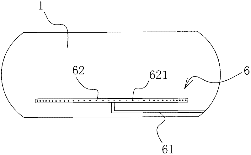
[0005] 2. The steam input structure is not reasonable enough. The steam is input from one end to the air distribution pipe with vent holes, which may easily lead to uneven pressure and heat in the entire pressure vessel, resulting in color difference, which seriously affects the quality of printing and dyeing.
[0006] 3. The side cover of the pressure vessel usually needs to be opened or closed manually, so the operation is time-consuming and laborious

Method used

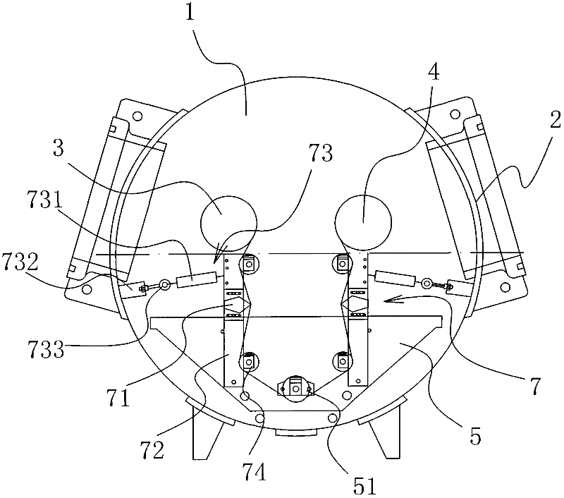
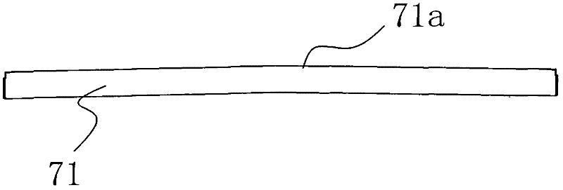

Image

  • High-temperature high-pressure dyejigger
  • High-temperature high-pressure dyejigger
  • High-temperature high-pressure dyejigger

Examples


Embodiment Construction

[0025] Such as figure 1 As shown, the high temperature and high pressure dyeing machine includes a pressure vessel 1, a window is opened on the side of the pressure vessel 1, a side cover 2 is arranged at the window, and an automatic sliding door mechanism is arranged between the pressure vessel 1 and the side cover 2. Such as Figure 4 and 5 As shown, the automatic sliding door mechanism includes a horizontally arranged walking beam 81 and a horizontally arranged suspension beam 82, the suspension beam 82 is provided with the side cover 2, and the suspension beam 82 and the walking beam 81 are provided with An electric driving structure 83 capable of driving the suspension beam 82 to move horizontally along the walking beam 81 .

[0026] The electric driving structure 83 includes a support frame 831 on which a traveling wheel 832 is arranged, and the traveling wheel 832 is connected to a driver 833 fixed on the support frame 831 . A transmission wheel 834 is provided betwe...


PUM


Abstract

The invention belongs to the technical field of printing and dyeing equipment, in particular to a high-temperature high-pressure dyejigger which solves the technical problems that the prior art is not reasonable enough in design, and the like. The high-temperature and high-pressure dyejigger comprises a pressure container, wherein the side part of the pressure container is provided with a window, and a side cover is arranged at the window; a first roller and a second roller are arranged in the pressure container, wherein a dye vat is arranged below the first roller and the second roller; a steam input mechanism is connected to the pressure container; the first roller and the second roller are respectively connected with a first frequency-conversion drive device and a second frequency-conversion drive device; a vertical tensioning mechanism is arranged between the first roller and the dye vat; and another vertical tensioning mechanism is arranged between the second roller and the dye vat. The high-temperature high-pressure dyejigger disclosed by the invention has the advantages of reasonable design, simple structure, difficulty in generating chromatic aberration, easiness in operation and use, time and labor saving, high working efficiency and capability of effectively ensuring the evenness of fabrics. According to the high-temperature high-pressure dyejigger, pressure balance and temperature evenness in the pressure container can be realized, the dyeing quality is effectively ensured, and the product quality is good.

Description

technical field [0001] The invention belongs to the technical field of printing and dyeing equipment, and in particular relates to a high-temperature and high-pressure dyeing jigger. Background technique [0002] Dye jigger is an intermittent dyeing machine, which can be divided into common dye jigger and high temperature and high pressure dyeing machine according to its working nature. The disadvantages of ordinary jiggers are that the linear speed of the fabric running is inconsistent, the tension is relatively high, and the labor intensity is relatively high. For this reason, people have designed high-temperature and high-pressure dyeing jiggers, and the dyeing process is completed in high-temperature and high-pressure airtight containers. For example, the Chinese patent literature discloses a high-temperature and high-pressure automatic refining jigger [application number: CN94214710.3], which is composed of a refining and dyeing cylinder and a fabric roll connected wit...

Claims


Application Information

Patent Timeline
Patent Type & Authority Applications(China)
IPC IPC(8): D06B3/32D06B23/00D06B23/04D06B23/20
Inventor 黄国表
Owner 骆玛丽
Why Eureka
Eureka Blog
Learn More