Method of adopting tool type clamp to support ground beam template side molds

A tool-type, ground-beam technology, which is applied in the fields of formwork/formwork/work frame, on-site preparation of building components, construction, etc., can solve the problems such as the tightness of extrusion between the formwork that cannot meet the control accuracy of beam section size, and achieves The effect of high recyclability, high turnover and long service life

Inactive Publication Date: 2012-06-13
CHINA CONSTR SIXTH ENG DIV CORP +1
View PDF8 Cites 8 Cited by
  • Summary
  • Abstract
  • Description
  • Claims
  • Application Information

AI Technical Summary

Problems solved by technology

In addition, when the sum of beam formwork plus keel and beam width dimensions does not match the modulus of the above-mentioned fixture design, it cannot meet the control accuracy of the beam section size and the extrusion tightness between the formwork

Method used


Image

  • Method of adopting tool type clamp to support ground beam template side molds
  • Method of adopting tool type clamp to support ground beam template side molds
  • Method of adopting tool type clamp to support ground beam template side molds

Examples


Embodiment 1

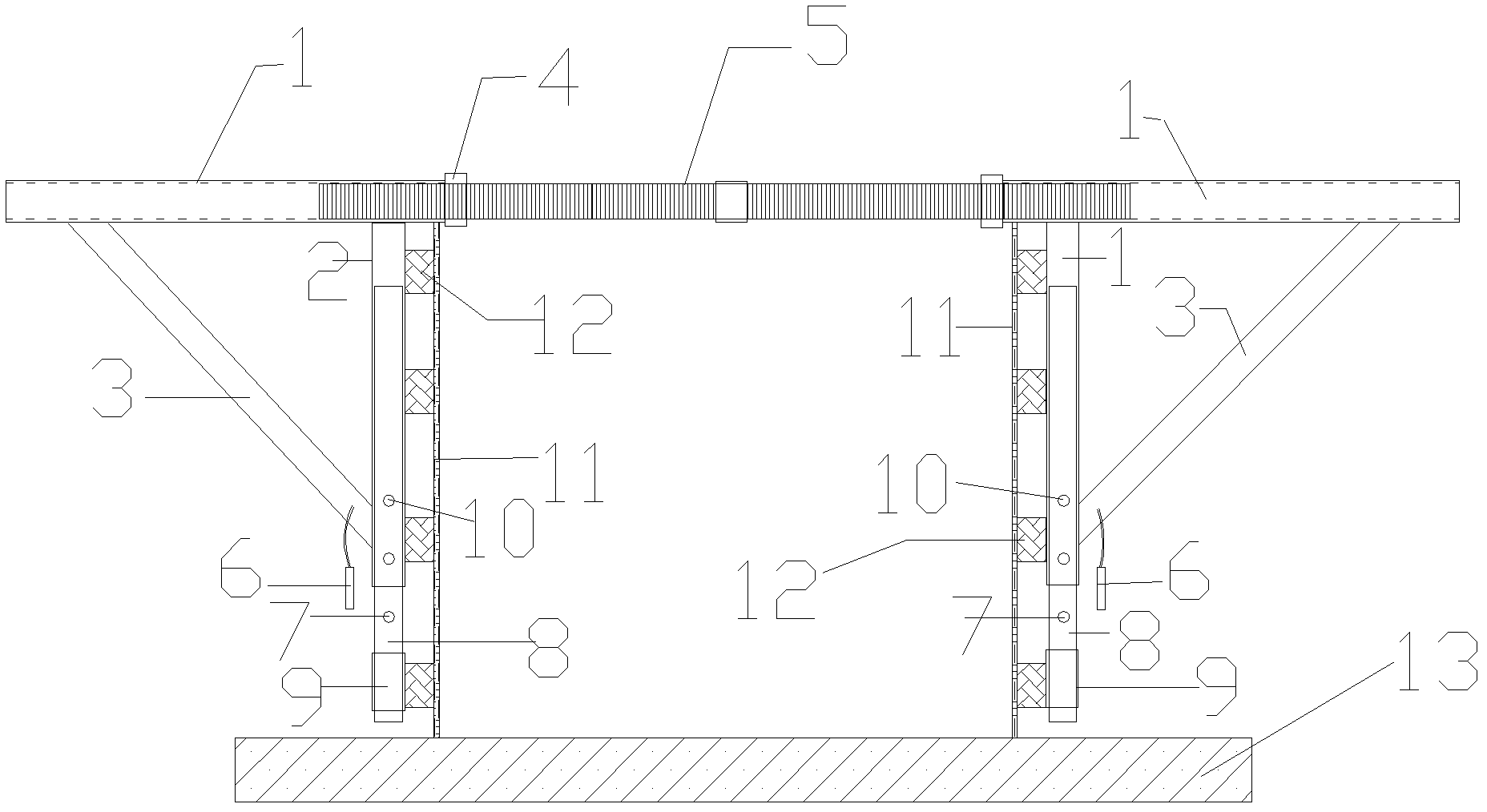
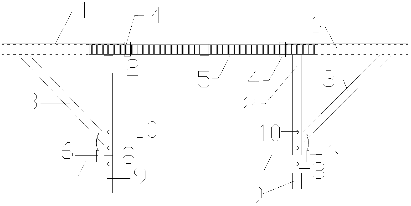
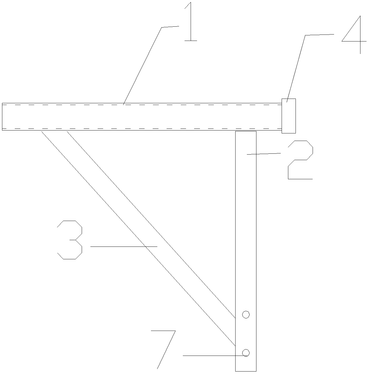
[0026] According to the size of the ground beam, select a fixed tripod consisting of horizontal 1, longitudinal rod 2, diagonal rod 3 and nut 4 suitable for the height of the ground beam, and select a screw 5 of appropriate length according to the width of the ground beam. The sliding rod 8 of the adjusting rod is inserted into the longitudinal rod 2 of the fixed tripod and assembled with the positioning pin 6 as a whole, and the screw rod 5 is connected with the two nuts 4 of the fixed tripod and the inner wire of the horizontal 2 to form the fixture of the invention.

[0027] Use the above fixtures for construction:

[0028] (a) The two side molds 11 of the ground beam provided with the outer longitudinal ribs 12 are erected on the ground mold 13 according to the ground beam positioning line; (b) The screw 5 of the fixture is installed on the top of the ground beam side mold and The two longitudinal rods of the fixture are respectively arranged outside the outer longitudinal corr...

Embodiment 2

[0031] According to the size of the ground beam, a stereotyped fixed tripod consisting of horizontal 1, longitudinal rod 2, diagonal rod 3 and nut 4 was selected to suit the height of the ground beam, and the screw 5 of appropriate length was selected according to the width of the ground beam. The sliding rod 8 of the adjusting rod is inserted into the longitudinal rod 2 of the fixed tripod and assembled with the positioning pin 6 as a whole, and the screw rod 5 is connected with the two nuts 4 of the fixed tripod and the inner wire of the horizontal 2 to form the fixture of the invention.

[0032] Use the above fixtures for construction:

[0033] (a) The two side molds 11 of the ground beam provided with the outer longitudinal ribs 12 are erected on the ground mold 13 according to the ground beam positioning line; (b) The screw 5 of the fixture is installed on the top of the ground beam side mold and The two longitudinal rods of the fixture are respectively arranged outside the ou...


PUM


Abstract

The invention discloses a method of adopting a tool type clamp to support a ground beam template side molds, which comprises the following steps: (a) erecting two side molds of a ground beam provided with outer longitudinal ridges on a floor mold according to a ground beam positioning line; (b) installing a screw rod of the clamp at the tops of the ground beam side molds and enabling two longitudinal rods of the clamp to be respectively arranged on the outer sides of the outer longitudinal ridges of the ground beam side molds; (c) adjusting the two longitudinal rods of the clamp to be aligned with different pin holes of sliding rods corresponding to the longitudinal rods, inserting positioning pins into the pin holes to perform fixing, and enabling reinforcing sleeve pipes arranged on the sliding rods and the outer longitudinal ridges arranged on the lowermost portions of the ground beam side molds to be at the same position; and (d) rotating a lead screw in threaded connection with two horizontal rods of the clamp, and enabling the two longitudinal rods and fixing sleeve pipes to be respectively squeezed closely with the outer longitudinal ridges of the ground beam side molds. The method of adopting the tool type clamp to support the ground beam template side molds is high in adaptability, reduces investment cost and is suitable for construction of a cast-in-place reinforced concrete ground beam.

Description

Technical field [0001] The invention relates to a method for supporting a side form of a ground beam formwork by using a tool-type clamp, which belongs to the field of building construction. It is suitable for reinforcing side formwork of reinforced concrete ground beams of various sizes. Background technique [0002] The support of the side form of the existing ground beam formwork generally adopts the outer corrugated steel pipe, the upper part of the formwork is fastened by the steel pipe snap-fitting or the opposite pull bolt, and the lower part is connected by the opposite pull bolt. This method has low work efficiency, and holes need to be made on the template at the place where the bolts are pulled, which affects the service life of the template. At the same time, because the ground beam is usually wider, there is not enough working surface to take out the lower tension bolts, which increases the construction cost. If a combined stereotype fixture is used, work efficienc...

Claims


Application Information

Patent Timeline
Patent Type & Authority Applications(China)
IPC IPC(8): E04G13/04
Inventor 张成才王存贵王文彪郭建东王丽梅凡春
Owner CHINA CONSTR SIXTH ENG DIV CORP
Why Eureka
Try Eureka