
Comprehensive parameter testing system of suspension type material transmitting device

A comprehensive parameter and material transmission technology, which is applied in the field of comprehensive parameter test system of suspended material transmission device, can solve the problems of power application influence, unstable operation of transmission system, power waste, etc., and achieve the effect of stable operation

Inactive Publication Date: 2012-06-13
BEIJING JIAOTONG UNIV
View PDF6 Cites 6 Cited by
  • Summary
  • Abstract
  • Description
  • Claims
  • Application Information

AI Technical Summary

Problems solved by technology

[0003] In order to enable the transmission device to transmit materials more efficiently, generally a fan with a relatively large power and a matching disc groove are selected to drive the conveyor belt. However, this structure will cause power waste when the material to be transmitted is relatively small.
For example, when transporting materials such as coal mines, in order to improve efficiency, high-power fans are selected. However, if there are fewer coal mines to be transported, only a small power is needed to drive the conveyor belt with less materials. In this way The use of high-power fans will cause power waste, and the arrangement and size of the air holes on the disk slot will also affect the power application
At the same time, the arrangement and size of the air holes on the current disk grooves make the air flow uneven, which leads to the unstable operation of the transmission system.

Method used


Image

  • Comprehensive parameter testing system of suspension type material transmitting device
  • Comprehensive parameter testing system of suspension type material transmitting device
  • Comprehensive parameter testing system of suspension type material transmitting device

Examples


Embodiment Construction

[0030] In order to make the above objects, features and advantages of the present application more obvious and understandable, the present application will be further described in detail below in conjunction with the accompanying drawings and specific implementation methods.

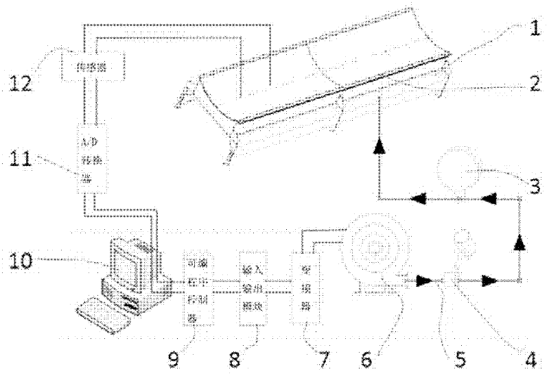
[0031] refer to figure 1 , shows a structural diagram of a comprehensive parameter testing system for a suspended material conveying device of the present application.

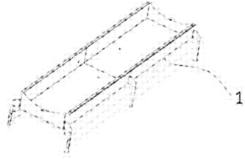
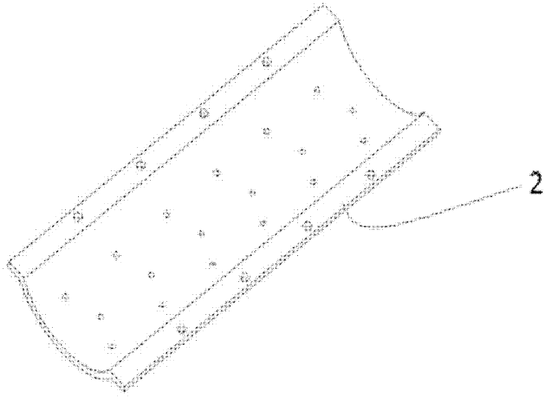
[0032] The system includes: a suspension conveyor test bench (1), a plurality of disk slots (2), a fan (6), a frequency converter (7), a PC (10), and a sensor (12), among which,

[0033] The disk groove (2) is installed on the suspension conveyor test bench (1), and one disk groove (2) is installed for each test, and the disk groove (2) has air holes;

[0034] A transmission belt is placed on the disk groove (2), the sensor (12) is installed on the transmission belt, the sensor (12) is connected with the PC (10), and the signal is trans...


PUM


Abstract

The invention provides a comprehensive parameter testing system of a suspension type material transmitting device, and the comprehensive parameter testing system comprises a suspension type conveyor experimental bench (1), a plurality of disc grooves (2), a fan (6), a frequency converter (7), a PC (personal computer) (10) and a sensor (12), wherein the disc grooves (2) are mounted on the suspension type conveyor experimental bench (1); one disc groove (2) is mounted for each test; the disc grooves (2) are provided with air holes; a transmitting belt is placed on the disc grooves (2); the sensor (12) is mounted on the transmitting belt; the sensor (12) is connected with the PC (10) and transfers a signal to the PC (10); the PC (10), the frequency converter (7) and the fan (6) are connected in sequence; the frequency of the frequency converter (7) is set through the PC (10); the frequency converter (7) is used for controlling the working frequency of the fan (6); and the fan (6) is connected with the suspension type conveyer experimental bench (1) and supplies air to the suspension type conveyer experimental bench (1) to drive the transmitting belt to drive.

Description

technical field [0001] The present application relates to the technical field of parameter testing, in particular to a comprehensive parameter testing system for a suspended material conveying device. Background technique [0002] Due to its advantages of convenient transmission, time-saving and labor-saving, the suspended material transmission device should be widely used in various industries. The transmission system sends airflow to the pan slot on the suspension conveyor test bench through the fan. There are air holes on the pan slot, and the air flow is transmitted to the conveyor belt on the pan slot through the air holes, driving the conveyor belt to move, so as to achieve the purpose of conveying materials. [0003] In order to enable the transmission device to carry out material transmission more efficiently, a fan with a relatively large power and a matching disc groove are generally selected to drive the conveyor belt, but this structure will cause power waste whe...

Claims


Application Information

Patent Timeline
IPC IPC(8): G01D21/02
Inventor 郭盛李志仁张东利黄伟刘建
Owner BEIJING JIAOTONG UNIV
Learn More