Vehicle mounted antenna lodging device controller

A vehicle-mounted antenna and controller technology, applied in program control, computer control, general control systems, etc., can solve the problems of not being able to display angle values ​​and faults, and not being able to control any angle of the antenna as required, and achieve high control accuracy and stability Effect

Inactive Publication Date: 2012-06-13
柳州市数控机床研究所
View PDF6 Cites 7 Cited by
  • Summary
  • Abstract
  • Description
  • Claims
  • Application Information

AI Technical Summary

Problems solved by technology

[0002] Due to the development of electronic information technology, there are more and more electronic equipment in communication vehicles, and the scope of application of antennas on vehicles is becoming wider and wider. In order to give full play to the performance of antennas, the antennas need to be erected higher on the vehicle body to facilitate transmission. and receiving signals, considering that ground communication vehicles will encounter obstacles when driving, the antenna needs to be in a lodging state when the vehicle is driving. The antenna lodging device controller is used to control the antenna to be vertical or parallel to the ground plane. At present, the function of the existing vehicle-mounted antenna lodging device controller in my country is relatively simple. It can only control the antenna to be vertical or parallel to the ground plane, and cannot control the antenna at any angle as required. Angle values ​​and faults cannot be displayed either

Method used


Image

  • Vehicle mounted antenna lodging device controller
  • Vehicle mounted antenna lodging device controller
  • Vehicle mounted antenna lodging device controller

Examples


Embodiment Construction

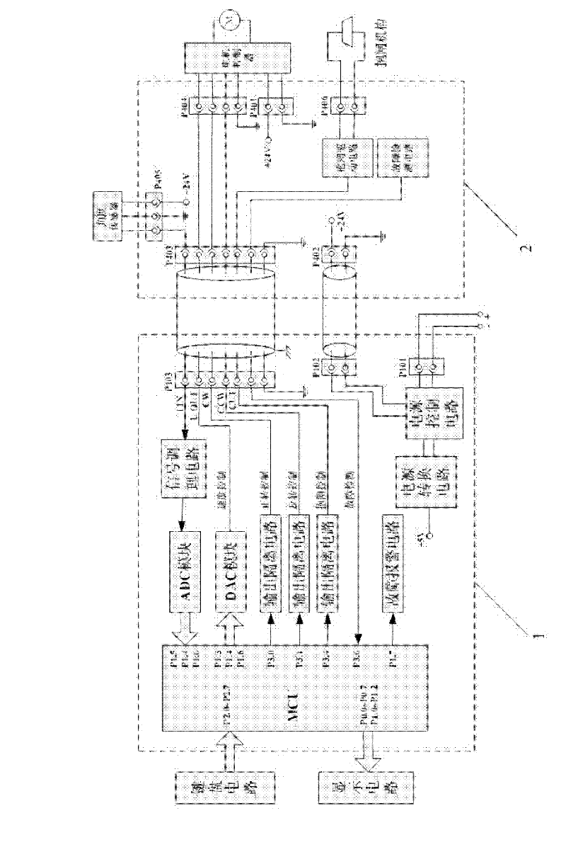
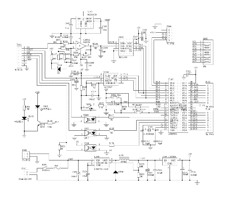
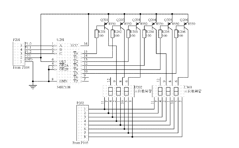
[0031] Such as Figure 1 to Figure 7 As shown, the vehicle-mounted antenna lodging device controller of the present invention (hereinafter referred to as "controller") includes a controller main board 1, a display circuit, a keyboard circuit and a signal adapter board 2. The controller also includes a body, the controller main board, display circuit, and keyboard circuit are all located in the body, and the signal adapter board is located in the vehicle-mounted antenna lodging device (hereinafter referred to as "lodging device") that is used in conjunction with the controller of the present invention.

[0032] The following is a brief introduction to the lodging device. The lodging device is driven by its rotating shaft. The antenna is fixedly connected to the lodging device. Therefore, the rotating antenna of the lodging device also rotates. The rotating shaft of the lodging device is driven by the motor. The motor is connected to the The motor controller on the motor control...


PUM


Abstract

The invention provides a vehicle mounted antenna lodging device controller, which relates to a controller. The vehicle mounted antenna lodging device controller comprises a controller mainboard, a display circuit, a keyboard circuit and a signal adapter plate, wherein the controller mainboard comprises a single chip, a signal conditioning circuit, an ADC (Analog To Digital Converter) module, a DAC (Digital To Analog Conventer) module, an output isolation module and a fault alarming circuit; the display circuit, the keyboard circuit and the fault alarming circuit are respectively connected with the single chip of the controller mainboard; an input end of the ADC module is connected with an output end of the signal conditioning circuit; an output end of the ADC module is connected with the single chip; input ends of the DAC module and the output isolation module are respectively connected with the signal adapter plate by cables; and the signal adapter plate comprises multiple connectorsand a brake driving circuit. By using the vehicle mounted antenna lodging device controller provided by the invention, the antenna can be controlled at any angle according to needs, the angle value of the antenna can be displayed in real time, and the fault code can be displayed to send out warning when the antenna lodging device has a fault, etc.

Description

technical field [0001] The invention relates to a controller, in particular to a controller for a vehicle-mounted antenna lodging device. Background technique [0002] Due to the development of electronic information technology, there are more and more electronic equipment in communication vehicles, and the scope of application of antennas on vehicles is becoming wider and wider. In order to give full play to the performance of antennas, the antennas need to be erected higher on the vehicle body to facilitate transmission. and receiving signals, considering that ground communication vehicles will encounter obstacles when driving, the antenna needs to be in a lodging state when the vehicle is driving. The antenna lodging device controller is used to control the antenna to be vertical or parallel to the ground plane. At present, the function of the existing vehicle-mounted antenna lodging device controller in my country is relatively simple. It can only control the antenna to be...

Claims


Application Information

Patent Timeline
Patent Type & Authority Applications(China)
IPC IPC(8): G05B19/042
Inventor 赖玉活温新权赖家胜金刚唐南房学明钱晓俊纪效鹏余静何俊方宁刘峰张树林
Owner 柳州市数控机床研究所
Why Eureka
Try Eureka