Light-emitting diode (LED) package and backlight module with LED package

A technology of LED encapsulation and backlight module, applied in electric light source, lighting device, fixed lighting device, etc., can solve the problems of increasing the cost of backlight module and so on

Inactive Publication Date: 2012-06-13
NANJING CEC PANDA LCD TECH
View PDF7 Cites 5 Cited by
  • Summary
  • Abstract
  • Description
  • Claims
  • Application Information

AI Technical Summary

Problems solved by technology

In order to improve the brightness of large viewing angles, a special optical film set is required, resulting in an increase in the cost of the backlight module

Method used


Image

  • Light-emitting diode (LED) package and backlight module with LED package
  • Light-emitting diode (LED) package and backlight module with LED package
  • Light-emitting diode (LED) package and backlight module with LED package

Examples


Embodiment 1

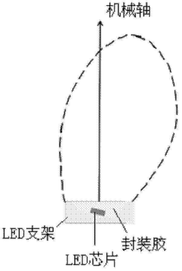
[0027] Such as Figure 4 As shown, the LED support includes a lower surface, two side surfaces, and two upper surfaces. The LED chip is arranged above the lower surface of the LED support. The encapsulation glue covers the LED support and the LED chip, and also includes a phosphor located in the encapsulation glue. (Not shown in the figure). In this embodiment, the slopes of the two side surfaces of the LED bracket are different, and the slope of the right side surface is smaller, which reflects the light emitted by the LED chip to the side surface to a large angle, and emits the LED package. The left side surface With a larger slope, the light emitted by the LED chip hitting the side surface is not easily refracted out of the LED package, so a larger ratio of light will be reflected off the LED package from the right side surface. The material of the LED bracket is a material with a reflective function (reflective material), which can be a plastic material or a ceramic materia...

Embodiment 2

[0029] Such as Figure 5 As shown, the difference between this embodiment and Embodiment 1 is that the slopes of the two side surfaces of the LED bracket are the same, and the lower surface of the LED bracket is an inclined plane. Due to the influence of the inclined plane, the light emitting behavior of the entire LED package is asymmetric.

Embodiment 3

[0031] Such as Image 6 As shown, the difference between this embodiment and embodiment 2 is that the lower surface of the LED bracket is a horizontal plane, and it also includes a secondary lens arranged above the upper surface of the LED bracket, and the secondary lens includes two asymmetric arc surfaces, The concave arc surface on the left transmits less light, and the convex arc surface on the right transmits more light, which makes the light-emitting behavior of the entire LED package asymmetric.

[0032] As shown in Fig. 3, Fig. 3(b) shows the light-emitting behavior of a traditional LED package. It can be seen that the light-emitting behavior is symmetrical with respect to the mechanical axis, that is, there are as many light rays on the left and right sides of the mechanical axis. Figures 3(a) and 3(c) show the light-emitting behavior of the LED package of the present invention. It can be seen that these two light-emitting behaviors are asymmetric with respect to the mech...


PUM


Abstract

The invention discloses a light-emitting diode (LED) package. The LED package comprises an LED bracket which comprises a lower surface, two side surfaces and two upper surfaces, an LED chip which is arranged above the lower surface of the LED bracket and packaging glue which coats the LED bracket and the LED chip. The LED package has asymmetrical light-emitting distribution. The invention also discloses a backlight module. A light-emitting source, namely the LED package has asymmetrical light-emitting action, and two groups of antisymmetrical light-emitting sources are alternately and repeatedly arranged, so that the spatial distribution of backlight lighting can be changed, and the conventional phenomenon of low brightness at a large visual angle can be effectively modified.

Description

Technical field [0001] The present invention relates to an LED (light emitting diode) package and a backlight module including the LED package. Background technique [0002] Due to the rapid progress in the production technology of TFT LCD (Thin Film Transistor Liquid Crystal Display), with its advantages of lightness, thinness, power saving and no radiation, TFT LCD is widely used in notebook computers, liquid crystal screens and TVs. However, since the liquid crystal panel is not a self-luminous display device, it needs to cooperate with the light source provided by the backlight module to display the image required by the liquid crystal panel. For direct-lit backlight modules, it usually includes: optical film set (Films), diffuser plate (Diffuser plate), reflector (reflector), back plate and light source (ie LED package), such as figure 1 Shown. [0003] The direct type backlight module uses the light emitted by the light source to undergo multiple refraction and reflection of...

Claims


Application Information

Patent Timeline
Patent Type & Authority Applications(China)
IPC IPC(8): H01L25/075H01L33/48H01L33/52F21S8/00G09G3/34
Inventor 曾威扬江政昇赵圣杰
Owner NANJING CEC PANDA LCD TECH
Why Eureka
Try Eureka