An input circuit for anti-reverse polarity protection

An input circuit, anti-reverse connection technology, applied in emergency protection circuit devices, electrical components and other directions, can solve the problems of increased volume and cost, energy loss, and the DC charging circuit cannot be protected against reverse polarity of the power supply for a long time, and achieves improved performance. Electric energy utilization efficiency, no energy loss effect

Active Publication Date: 2016-10-19
ZHUZHOU CSR TIMES ELECTRIC CO LTD
View PDF3 Cites 0 Cited by
  • Summary
  • Abstract
  • Description
  • Claims
  • Application Information

AI Technical Summary

Problems solved by technology

[0006] But when figure 1 In the shown DC charging circuit, since the first diode D1 is connected to the branch of the main circuit, when the DC input device works normally, there will be current flowing through the first diode D1, so that the first diode D1 will Cause continuous energy loss, especially when the current flowing through the branch of the main circuit is large, this energy loss will be greater, thereby reducing the power utilization efficiency of the DC input device; while in figure 2 In the DC charging circuit shown, although the reverse polarity protection of the power supply can be realized through the first diode D1, if the polarity of the power supply is reversed for a long time, the electric energy of the power supply will be added to the first resistor R1 for a long time. There is continuous energy loss on the first resistor, which may cause damage to the first resistor R1 and even the circuit. Therefore, figure 2 The DC charging circuit shown cannot be protected against reverse polarity of the power supply for a long time
[0007] In the above two circuits, the first diode may have a long-term current passing through it, resulting in continuous loss, and there are higher requirements for its type selection and heat dissipation requirements, which will inevitably increase the volume and cost.

Method used


Image

  • An input circuit for anti-reverse polarity protection
  • An input circuit for anti-reverse polarity protection
  • An input circuit for anti-reverse polarity protection

Examples


Embodiment Construction

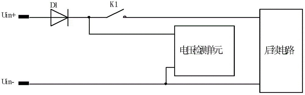
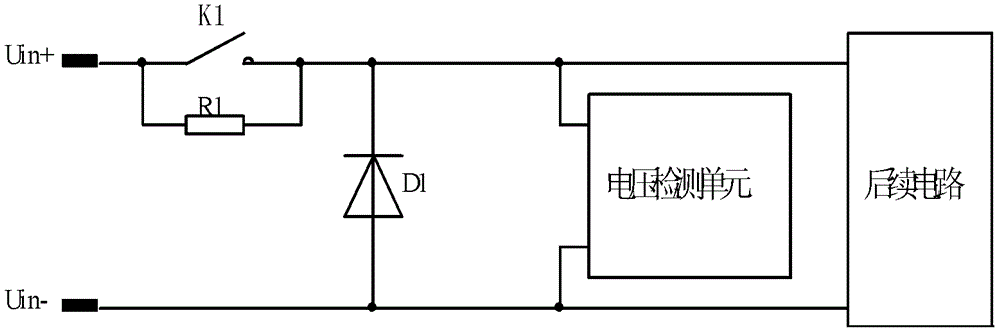
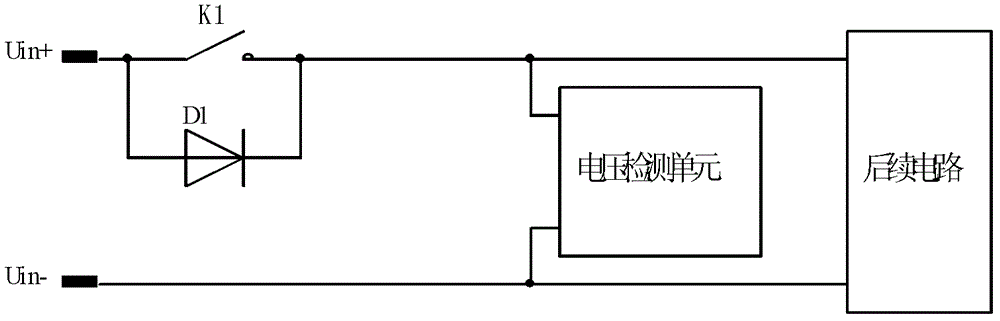
[0038] The DC charging circuit of the embodiment of the present invention includes: the first input end of the input circuit is connected to the first output end of the input circuit through a first switch; the first diode is connected in parallel with the first switch; the second input end of the input circuit is connected to the input The second output terminal of the circuit; the first input terminal and the second input terminal of the voltage detection unit are respectively connected to the first output terminal and the second output terminal of the input circuit; the voltage detection unit is used for: detecting two input circuits Whether there is a voltage between the output terminals, the first switch is controlled to be turned on and off according to the detection result.

[0039] Hereinafter, the implementation of the DC charging circuit according to the embodiment of the present invention will be described in detail in conjunction with the accompanying drawings.

[...


PUM


Abstract

The invention discloses an anti-reverse connection input circuit and a DC input device. The input circuit comprises: the first input end of the input circuit is connected to the first output end of the input circuit through a first switch; the first diode and the second A switch is connected in parallel; the second input end of the input circuit is connected to the second output end of the input circuit; the first input end and the second input end of the voltage detection unit are respectively connected to the first output end and the second output end of the input circuit; The voltage detection unit is used for: detecting whether there is a voltage between the two output terminals of the input circuit, and controlling the closing and opening of the first switch according to the detection result. The input circuit can improve the electric energy utilization efficiency of the DC input equipment, and can effectively protect the reverse polarity of the power supply of the DC input equipment for a long time.

Description

technical field [0001] The invention relates to anti-reverse connection technology, in particular to an input circuit for anti-reverse connection protection. Background technique [0002] Inside the DC input device, in order to prevent the polarity of the power supply connected to the two input terminals of the DC input device from being reversed, causing damage to the components or lines of the DC input device, a Diodes to protect DC input devices by utilizing the single-phase conductivity of diodes. [0003] figure 1 It is a schematic diagram of the input circuit structure of a DC input device in the prior art, such as figure 1 As shown, the input circuit includes: the first input end of the input circuit is connected to the first output end of the input circuit through the first diode D1 and the first switch K1 connected in series; the second input end of the input circuit is connected to the The second output terminal, and the two input terminals of the voltage detect...

Claims


Application Information

Patent Timeline
Patent Type & Authority Patents(China)
IPC IPC(8): H02H11/00
Inventor 谢湘剑林文彪刘方华羊利芬李华
Owner ZHUZHOU CSR TIMES ELECTRIC CO LTD
Why Eureka
Try Eureka