Energy-saving air power source system of wood drying device

An aerodynamic, wood drying technology, applied in the direction of drying gas arrangement, humidity control wood, wood processing appliances, etc., can solve the problems of short service life of fans, high power consumption of motors, low efficiency of fans, etc. The effect of low motor power consumption and power consumption reduction

Inactive Publication Date: 2010-01-13
NORTHEAST FORESTRY UNIVERSITY
View PDF0 Cites 6 Cited by
  • Summary
  • Abstract
  • Description
  • Claims
  • Application Information

AI Technical Summary

Problems solved by technology

[0004] The purpose of the present invention is to provide an energy-saving air power source system for wood drying devices to solve the problems of complex structure, low fan efficiency, large motor power consumption, large power consumption, short service life of fans and stable air power in existing conventional wood drying devices. sex problem

Method used


Image

  • Energy-saving air power source system of wood drying device
  • Energy-saving air power source system of wood drying device
  • Energy-saving air power source system of wood drying device

Examples


specific Embodiment approach 1

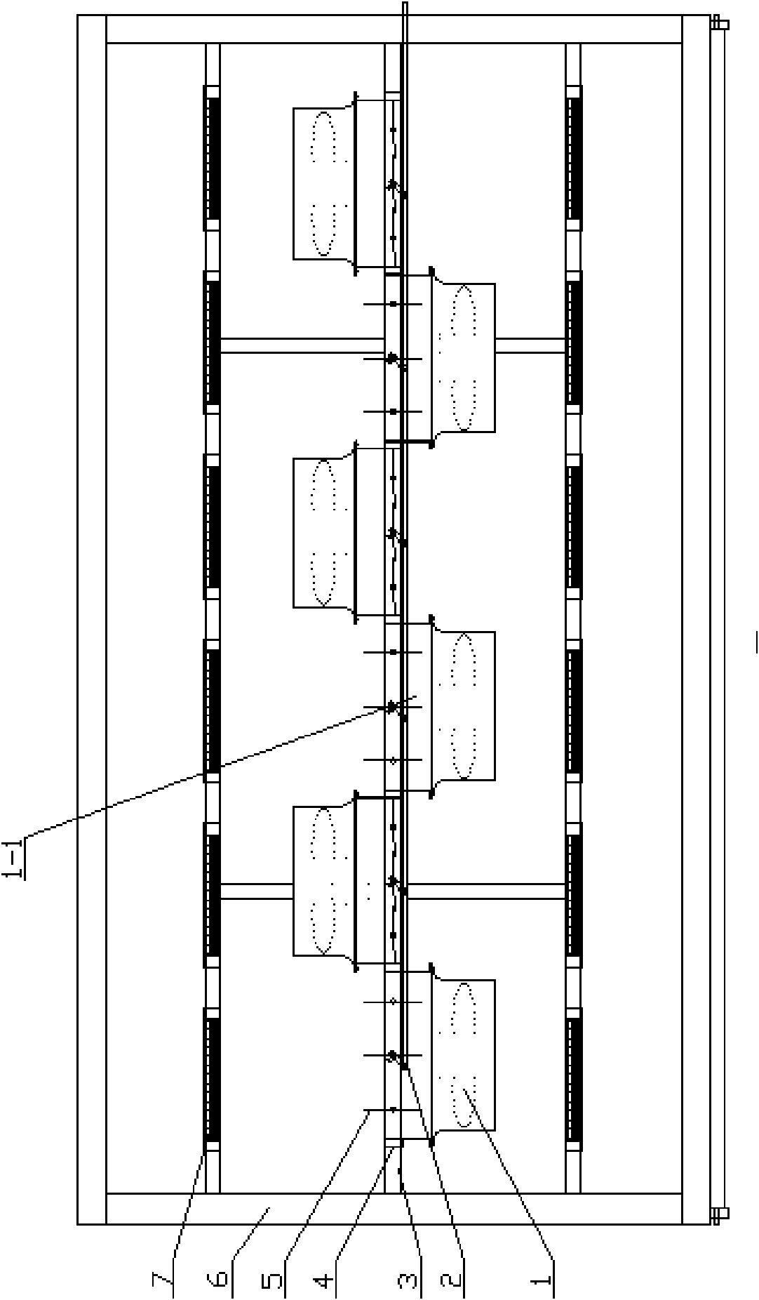
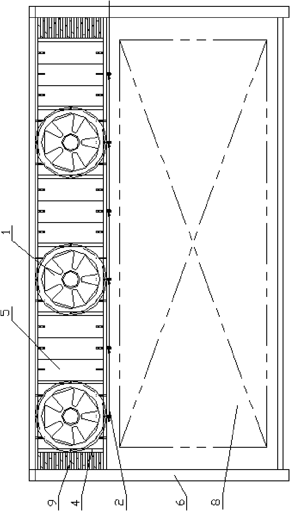
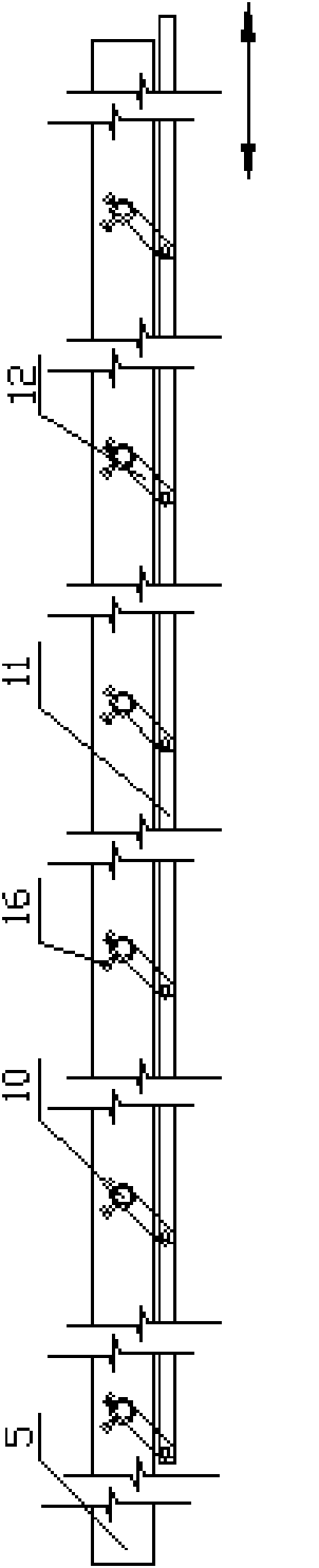
[0008] Specific implementation mode one: combine Figure 1 to Figure 9 Describe this embodiment, the aerodynamic source system described in this embodiment includes a plurality of fans; the aerodynamic source system also includes a bracket 3, a plurality of louvers, a shutter control mechanism 2 and a plurality of fan baffles 9; It is a one-way axial flow fan 1, and each louver is made up of a plurality of louver blades 5, a louver frame 4 and a synchronous linkage mechanism; the synchronous linkage mechanism consists of a plurality of first linkage handles 13, a plurality of second linkage handles 14 and The first linkage rod 15 is formed; a plurality of louver blades 5 are arranged in the louver frame 4 along the width direction of the drying chamber 6, and each louver frame 4 is fixed on the support 3, and the support 3 is fixed on the length direction of the drying chamber 6. In the drying chamber 6, each louver blade 5 in each louver is fixedly connected to one end of a f...

specific Embodiment approach 2

[0010] Specific implementation mode two: combination figure 1 and figure 2 To illustrate this embodiment, the bracket 3 in this embodiment is arranged on the central axis of the drying chamber 6 in the longitudinal direction, and the plurality of louvers are arranged in a line and located on the central axis of the drying chamber 6 in the longitudinal direction. The axial flow fan 1 is arranged in a staggered manner relative to the support 3 . This kind of layout causes different airflow resistances due to the wall distance and airflow stroke difference between the inlet and outlet of the unidirectional axial flow fan 1 and the air outlet of the drying chamber 6, so that the wind speed obtained at the inlet side of the timber stack is not the same. Others are the same as in the first embodiment.

specific Embodiment approach 3

[0011] Specific implementation mode three: combination Figure 9 Describe this embodiment, the support 3 of this embodiment is arranged on the central axis of the drying chamber 6 in the longitudinal direction, and the plurality of unidirectional axial flow fans 1 are arranged in a line on the central axis of the support 3 .

[0012] The difference between the present embodiment and the second specific embodiment is not obvious in the influence of the two layouts on the air circulation rate. The shape, size and quantity of the louver blades 5 can be adjusted and determined according to actual conditions. Others are the same as in the first embodiment.


PUM


Abstract

The invention discloses an energy-saving air power source system of a wood drying device and relates to an air power source system of a wood drying device, aiming at the problems of a conventional wood drying device, such as complex structure, low efficiency of fans, high power consumption of a motor, short fan service life, and the like. A plurality of blades of a louver are arranged in a louver frame along the direction of the width of a drying chamber. The louver frame is fixedly installed on a bracket which is fixed in the drying chamber. One end of a first linkage handle is fixedly connected with the blades of the louver, and the other end of the first linkage handle is hinged with a second linkage handle; the second linkage handle is fixedly connected with a first linkage rod; a rotating shaft is fixed on the blade of the louver, one end of a rotating handle is fixedly connected with the rotating shaft, and the other end of the rotating handle is hinged with a second linkage rod; a plurality of one-way propeller fans are fixedly installed on the bracket, and the air outlets of the one-way propeller fans correspond to the louver, and the air outlets of every two adjacent one-way propeller fans are opposite to each other. The invention has the advantages of simple structure, high efficiency of fans, low power consumption of the motor, low electrical energy consumption, long service life of fans and good stability.

Description

technical field [0001] The invention relates to an air power source system of a wood drying device. Background technique [0002] Wood drying is an indispensable and important production link in the process of processing wood into various civil and industrial wood products. The conventional wood drying method is currently the most commonly used drying method. Conventional wood drying is to stack wood according to certain requirements in a conventional wood drying device (or called drying room, drying kiln or drying room, etc.) equipped with forced air circulation fans, heat exchangers, humidity control and detection devices. , according to the specified process benchmarks and requirements, make the humid air as the drying medium flow through the heat exchanger and the surface of the wood according to certain rules, transfer the heat to the wood, and at the same time mix the moisture evaporated from the wood into the wet air and discharge it to the outdoor. In this process ...

Claims


Application Information

Patent Timeline
Patent Type & Authority Applications(China)
IPC IPC(8): F26B21/04B27K1/02
Inventor 陈广元李磊
Owner NORTHEAST FORESTRY UNIVERSITY
Why Eureka
Try Eureka