Micro-grid region energy control system and control method

An energy control system and regional energy technology, which can be used in AC network circuits, AC network load balancing, single-network parallel feeding arrangements, etc., and can solve problems such as poor stability.

Active Publication Date: 2017-11-17
GREE ELECTRIC APPLIANCES INC
View PDF3 Cites 6 Cited by
  • Summary
  • Abstract
  • Description
  • Claims
  • Application Information

AI Technical Summary

Problems solved by technology

[0004] The present invention provides a micro-grid regional energy control system and control method to at least solve the problem of poor stability of the micro-grid energy control system in the prior art

Method used


Image

  • Micro-grid region energy control system and control method
  • Micro-grid region energy control system and control method
  • Micro-grid region energy control system and control method

Examples


Embodiment 1

[0037] The micro-grid regional energy control system provided by the present invention will be described below with reference to the accompanying drawings.

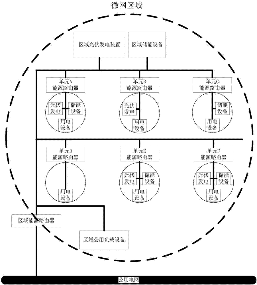
[0038] figure 1 It shows an optional structural schematic diagram of the microgrid area energy control system according to the embodiment of the present invention, wherein, preferably, the microgrid area can be understood as a residential area, and the corresponding units A to F are the households in the area The micro-grid area can also be understood as a factory, and the corresponding units A to F are workshop units in the factory; the micro-grid area can also be understood as an industrial park, and the corresponding units A to F are the park inside the factory.

[0039] like figure 1 As shown, the microgrid area includes one or more microgrid units, and the microgrid unit includes a unit energy router (see unit A energy router, unit B energy router...unit F energy router in the figure), new energy generation equipme...

Embodiment 2

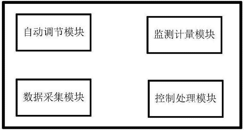
[0042] Based on the micro-grid regional energy control system provided in the above-mentioned embodiment 1, the optional embodiment 2 of the present invention also provides a preferred implementation of the unit energy router in the micro-grid regional energy control system, specifically, figure 2 It shows an optional structural block diagram of the unit energy router in the microgrid area energy control system, as shown in figure 2 As shown, the Cell Energy Router consists of:

[0043] (1) Automatic adjustment module: automatically control the real-time energy and power balance in the system unit to maintain system stability;

[0044] (2) Data acquisition module: collect the output power of photovoltaic power generation in real time, that is, the real-time power generation Wg; the power consumption of electric equipment is the real-time power consumption Wl; Discharge capacity Wd, and remaining capacity SOC;

[0045] (3) Monitoring and metering module: analyze the real-ti...

Embodiment 3

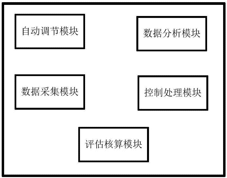
[0049] Based on the micro-grid regional energy control system provided in the above-mentioned embodiment 1, the optional embodiment 3 of the present invention also provides a preferred implementation of the regional energy router in the micro-grid regional energy control system, specifically, image 3 It shows an optional structural block diagram of the area energy router in the microgrid area energy control system, as shown in image 3 As shown, the District Energy Router includes:

[0050] (1) Automatic adjustment module: automatically control the real-time energy and power balance of the system in the area to maintain system stability;

[0051] (2) Data analysis module: receive the energy demand and supply information sent by the energy router of the unit, and summarize and analyze the relationship between supply and demand respectively. At the same time, combined with the peak-valley adjustment demand of the public power grid, determine the real-time control parameter Pc, ...


PUM


Abstract

The invention discloses a micro-grid region energy control system and control method. A micro-grid region comprises one or more micro-grid units; each micro-grid unit comprises a unit energy router and at least one set of new energy power generation equipment, energy storage equipment and electricity utilization equipment; the micro-grid region is provided with a region energy router; the micro-grid region is connected with a public power grid through the region energy router; the micro-grid region is provided with a region new energy power generation device and region energy storage equipment which are shared by the multiple micro-grid units; and the region new energy power generation device and the region energy storage equipment are connected with the region energy router. The micro-grid region energy control system solves the problem that a micro-grid energy control system is relatively low in stability in the prior art, meets a peak-alternation operation requirement of a power grid, reduces the electricity utilization cost and also improves the utilization efficiency of new energy power generation.

Description

technical field [0001] The present invention relates to the technical field of micro-grid energy control, in particular to a micro-grid area energy control system and control method. Background technique [0002] Judging from the development trend of energy use, traditional mineral energy pollutes the environment more and more seriously, and its overall use ratio will be more and more restricted; new energy technologies are developing rapidly and their costs are getting cheaper and cheaper. Therefore, the development and utilization of new energy is on the rise. However, the disadvantage of new energy sources, such as photovoltaic power generation and wind power, is that the output power cannot be supplied stably. This leads to the phenomenon of limiting photovoltaic output, abandoning wind and other new energy waste and insufficient utilization. [0003] Aiming at the problem of poor stability of the microgrid energy control system in related technologies, no effective so...

Claims


Application Information

Patent Timeline
Patent Type & Authority Applications(China)
IPC IPC(8): H02J3/38H02J3/46H02J3/28
CPCH02J3/28H02J3/382H02J3/46
Inventor 文武任鹏赵志刚罗晓王灵军蒋世用张雪芬
Owner GREE ELECTRIC APPLIANCES INC
Why Eureka
Try Eureka