H-bridge driving circuit

A bridge drive circuit and circuit technology, applied in the field of excitation or armature current control, etc., can solve problems such as hindering the output frequency of the H bridge drive circuit, achieve the effect of accelerating the closing speed and meeting the driving demand

Inactive Publication Date: 2012-06-13
BEIJING JIAOTONG UNIV
View PDF4 Cites 21 Cited by
  • Summary
  • Abstract
  • Description
  • Claims
  • Application Information

AI Technical Summary

Problems solved by technology

The capacity of the capacitive effect generally ranges from hundreds of PF to thousands of PF. The existence of junction capacitance delays the rise and fall time of the gate drive voltage of the MOS transistor, thus hindering the increase of the output frequency of the H-bridge drive circuit.

Method used


Image

  • H-bridge driving circuit
  • H-bridge driving circuit
  • H-bridge driving circuit

Examples


Embodiment Construction

[0058] In order to make the above objects, features and advantages of the present application more obvious and comprehensible, the present application will be further described in detail below in conjunction with the accompanying drawings and specific implementation methods.

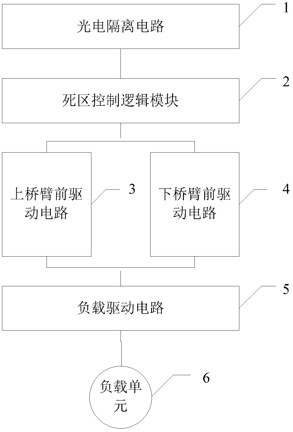
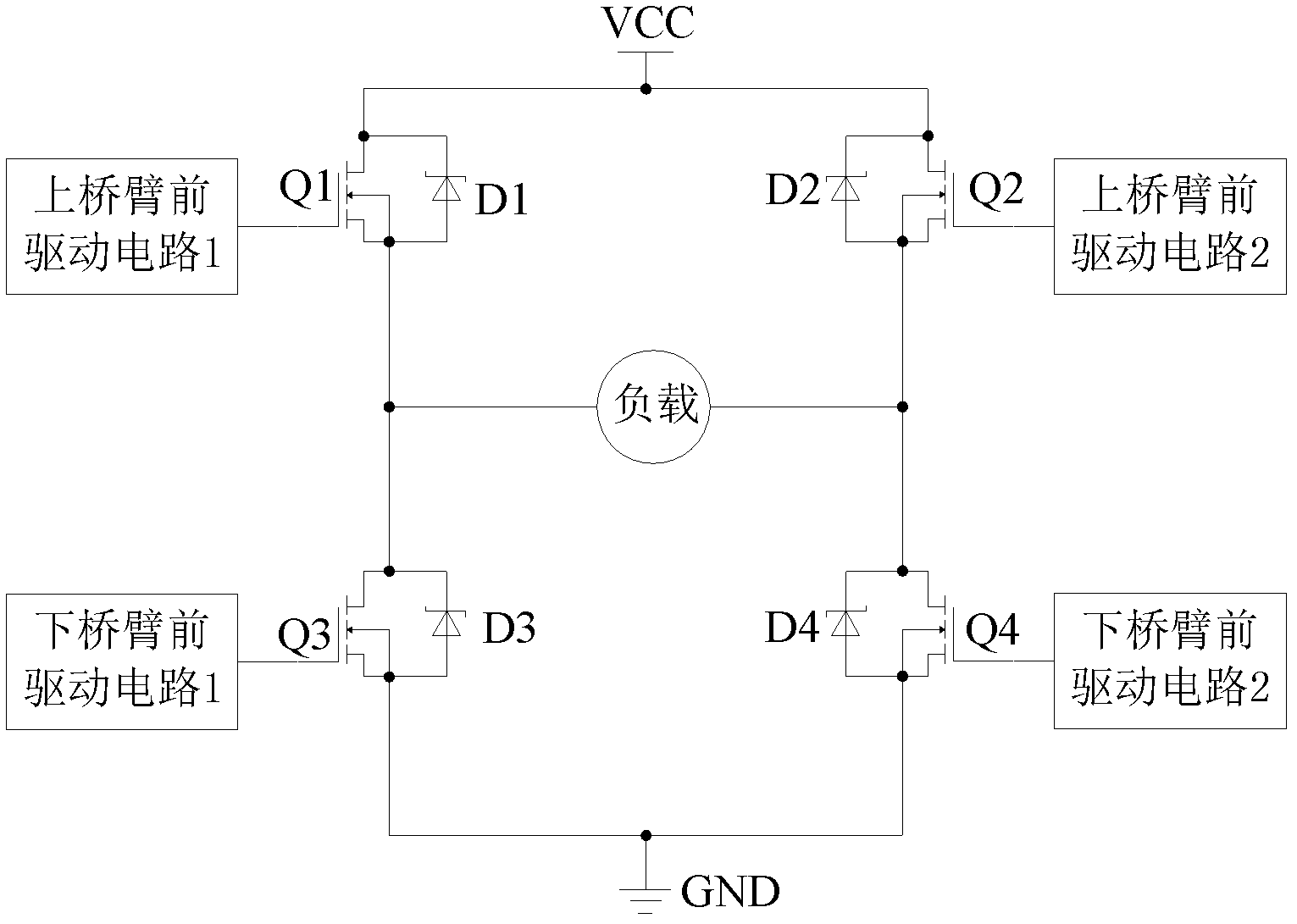
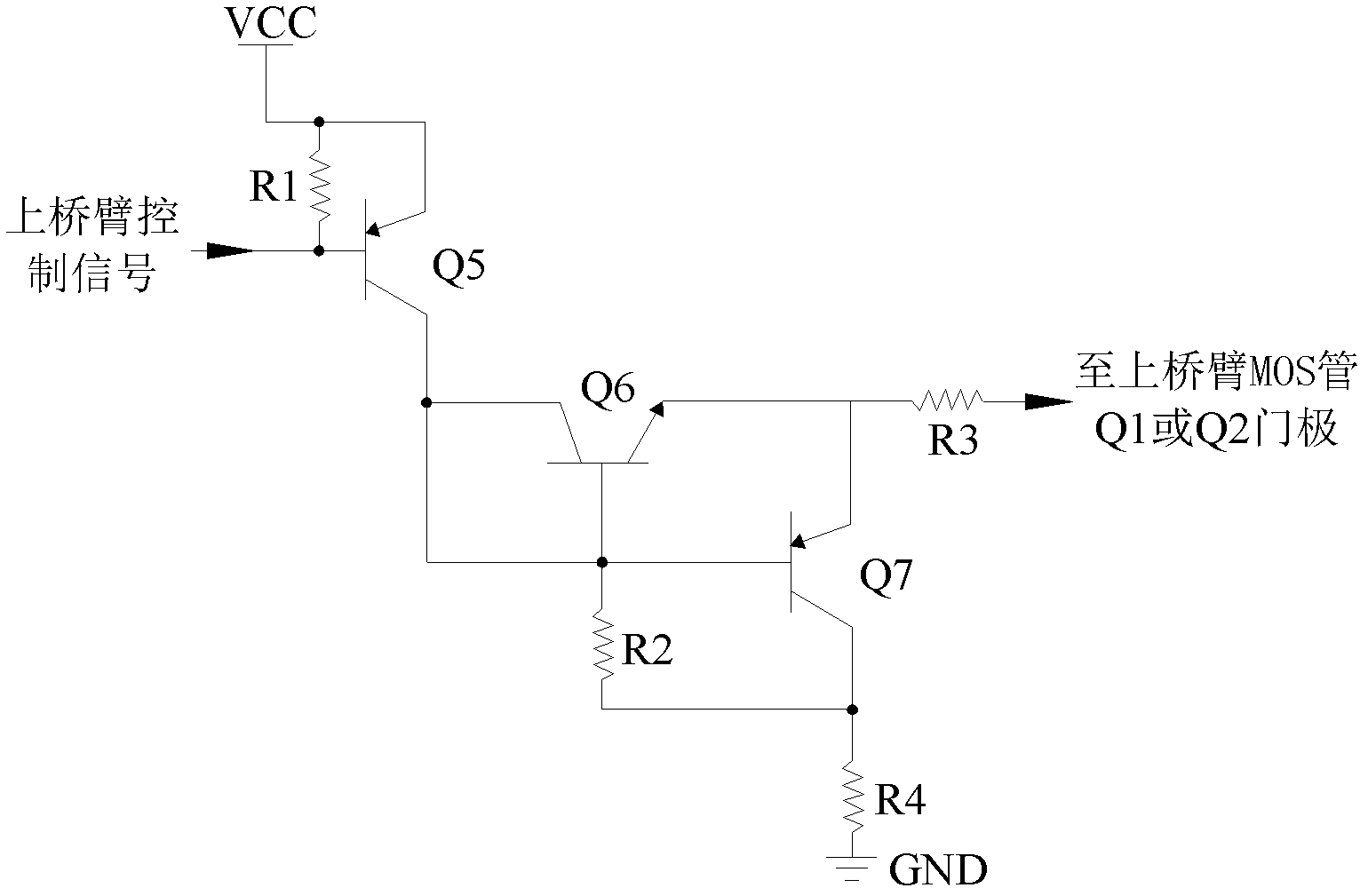
[0059] In the prior art, when the H-bridge drive circuit is turned off, there is a large junction capacitance between the gate and the source of the MOS transistor, that is, when the voltage at both ends of the load unit changes, the load unit exhibits a capacitive effect. The existence of the junction capacitance delays the rise and fall time of the gate drive voltage of the MOS transistor. In this application, a discharge circuit is added at the gate of the MOS tube to form a front drive circuit of the MOS tube, so as to speed up the discharge speed of the MOS tube and increase the closing speed of the MOS tube. Therefore, the capacitive effect of the load unit of the H-bridge driving circuit when the ...


PUM


Abstract

The invention provides an H-bridge driving circuit. The circuit is characterized by comprising the following steps that: a photoelectric isolating circuit converts a received first pulse width modulation (PWM) signal into a second PWM signal and transmits the second PWM signal to a dead zone control logic module; the dead zone control logic module sets dead zone information according to the second PWM signal, and generates an upper bridge arm control signal and a lower bridge arm control signal according to the dead zone information and the second PWM signal, and the dead zone control logic module transmits the upper bridge arm control signal to an upper bridge arm front driving circuit and transmits the lower bridge arm control signal to a lower bridge arm front driving circuit; and the upper bridge arm front driving circuit and the lower bridge arm front driving circuit control the operation state alternation of a load driving circuit according to the upper bridge arm control signal and the lower bridge arm control signal respectively. The circuit can avoid the capacity effect in the voltage change process of an H-bridge circuit load unit and the output frequency of the H-bridge driving circuit can be increased.

Description

technical field [0001] The present application relates to the technical field of drive circuits, in particular to an H-bridge drive circuit. Background technique [0002] The H-bridge drive circuit is a typical DC motor control circuit. The H-bridge motor drive circuit includes 4 triodes and a motor. To make the motor run, a pair of triodes on the diagonal must be turned on. Depending on the conduction of different transistor pairs, current may flow through the motor from left to right or from right to left, thereby controlling the direction of rotation of the motor. [0003] In practical applications, the H-bridge drive circuit usually uses PWM (Pulse Width Modulation) mode for low-power DC drive. It is widely used because of its simple structure, high efficiency and low cost. The H-bridge drive circuit generally uses 4 MOS tubes as the drive chip to form the 4 bridge arms of the H-bridge. At present, the H-bridge integrated circuit drive method is widely used, that is,...

Claims


Application Information

Patent Timeline
Patent Type & Authority Applications(China)
IPC IPC(8): H02P7/28
Inventor 沈海阔吴荐智少丹聂蒙
Owner BEIJING JIAOTONG UNIV
Why Eureka
Try Eureka