Long-range conical high-flow-rate pneumatic nozzle

A long-range, high-flow technology, applied in the direction of spraying devices, spraying devices, liquid spraying devices, etc., can solve the problems of small water flow, low vacuum efficiency, small work area, etc., and achieve the expansion of spraying angle, long range and high efficiency. high effect

Inactive Publication Date: 2012-06-20
江苏博际环境工程科技有限公司
View PDF7 Cites 2 Cited by
  • Summary
  • Abstract
  • Description
  • Claims
  • Application Information

AI Technical Summary

Problems solved by technology

[0004]At present, the typical conical pneumatic nozzle is like a paint spray gun nozzle. Its main disadvantage is: due to the structure of the nozzle, gas and water are mixed outside the end, and the gas diffuses quickly after being injected. 2. The working area for generating vacuum is small, and the efficiency of the vacuum generated by the periphery of the gas jet is low, so the sprayed water flow rate is small (a few liters per hour); because the water mist after collision and mixing has no guide section, the range is short (1 meters)

Method used


Image

  • Long-range conical high-flow-rate pneumatic nozzle
  • Long-range conical high-flow-rate pneumatic nozzle
  • Long-range conical high-flow-rate pneumatic nozzle

Examples


Embodiment Construction

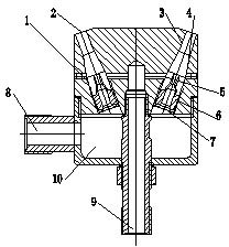
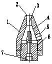
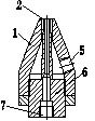
[0017] Each nozzle of the present invention comprises the pneumatic nozzle 7 that is provided with air inlet 6, and the outside of pneumatic nozzle 6 is provided with and cooperates pneumatic nozzle body 1, and the side wall of pneumatic nozzle body 1 is provided with water inlet 5, and the air nozzle body 6 The air outlet is arranged in the tapered section 4; the distance between the air outlet and the water mist outlet 2 is 2.5-3.5 times of the water mist outlet aperture, preferably 3 times.

[0018] The working process of each nozzle of the present invention is: the gas is input by the air inlet 7 of the pneumatic nozzle 6, the gas is ejected at a high speed through the outlet of the pneumatic nozzle 6, and the periphery of the gas jet produces a vacuum effect, that is, a vacuum zone (negative pressure) is formed. The vacuum area is connected with the water inlet chamber, and the water will be automatically inhaled and collided with air to mix and atomize, and then the mixed...


PUM


Abstract

The invention relates to a long-range conical high-flow-rate pneumatic nozzle, which comprises a plurality of pneumatic nozzles, wherein each pneumatic nozzle has the following structural form: the pneumatic nozzle comprises a pneumatic nozzle body and a pneumatic spray head; the pneumatic nozzle body is provided with a water inlet and a water mist outlet; the pneumatic spray head is provided with an air inlet; an air outlet of the pneumatic nozzle is formed in a cavity of the pneumatic nozzle body; positions of the water inlet and the air outlet correspond to each other; each pneumatic nozzle is circumferentially and uniformly arranged on a mounting disc at a certain inclination angle; the central position of the mounting disc is connected with a water inlet pipe; the water inlet pipe is communicated with each water inlet through a water inlet passage; and the lower part of the mounting disc is provided with an air cavity which is communicated with the air inlet of each pneumatic nozzle. The invention provides the long-range conical high-flow-rate pneumatic nozzle with large injection, long range and wide injection range.

Description

technical field [0001] The invention relates to a nozzle, which is mainly used in environments such as water mist and dust reduction at the tank inversion operation point in the steelmaking process. Background technique [0002] At present, conical pneumatic nozzles have been used in some cases, but they cannot meet special application occasions. Such as water mist dust reduction at the canning operation point in the steelmaking process; water mist dust reduction at the blast furnace tapping nozzle operation point. At these operating points, it is required that during the working process of the water mist nozzle, in the event of any failure in the control system, the nozzle mouth must not spray or flow out of the water column, otherwise there will be a safety accident or a major safety accident; therefore, the water mist nozzle must be kept away from Spraying is carried out 3~5m away from the operating point; the process of water mist dust reduction requires sufficient wate...

Claims


Application Information

Patent Timeline
Patent Type & Authority Applications(China)
IPC IPC(8): B05B7/04B05B1/06
Inventor 李有怀庄永顺孙廷宇
Owner 江苏博际环境工程科技有限公司
Why Eureka
Try Eureka