Mold locking shaft assembly lifting and shifting device

A technology of a toggle device and a shaft assembly is applied in the field of the lifting and toggle device of the clamping shaft assembly, which can solve the problems of increased moment of inertia and centrifugal force, shutdown of the blowing machine, bending deformation of the clamping shaft, etc., so as to reduce the moment of inertia, The effect of reducing centrifugal force and reducing weight

Active Publication Date: 2012-06-20
GUANGZHOU TECH LONG PACKAGING MACHINERY CO LTD
View PDF7 Cites 7 Cited by
  • Summary
  • Abstract
  • Description
  • Claims
  • Application Information

AI Technical Summary

Problems solved by technology

Although this kind of mold locking mechanism can better meet the mold locking requirements of medium and low speed blow molding machines, it cannot meet the mold locking requirements of fully automatic high-speed blow molding machines. The reasons are: 1. In the case of high-speed operation of the blow molding machine Under the circumstances, the clamping shaft and the guide shaft assembly rise and fall at the same time, and interference (suffocation) often occurs, resulting in unsmooth opening and closing of the mold base. In severe cases, it can cause the blowing machine to stop and increase the failure rate of the blowing machine
2. A guide shaft assembly 200 is added to the clamping mechanism, which increases the weight of the blowing main machine, increases the corresponding moment of inertia and centrifugal force of the main machine, and restricts the running speed of the fully automatic high-speed blow molding machine
3. When the first roller 301 runs to the mold clamping guide rail, due to the inertial force, an interactive impact force will be generated between the first roller 301 and the mold clamping guide rail. The clamping shaft is bent and deformed. On the one hand, this bending deformation will make it easier to interfere between the clamping shaft and the guide shaft assembly, causing the clamping shaft to suffocate and eventually stop the blow molding machine. On the other hand, it will aggravate the The wear of the clamping shaft greatly shortens the service life of the clamping shaft

Method used


Image

  • Mold locking shaft assembly lifting and shifting device
  • Mold locking shaft assembly lifting and shifting device
  • Mold locking shaft assembly lifting and shifting device

Examples


Embodiment Construction

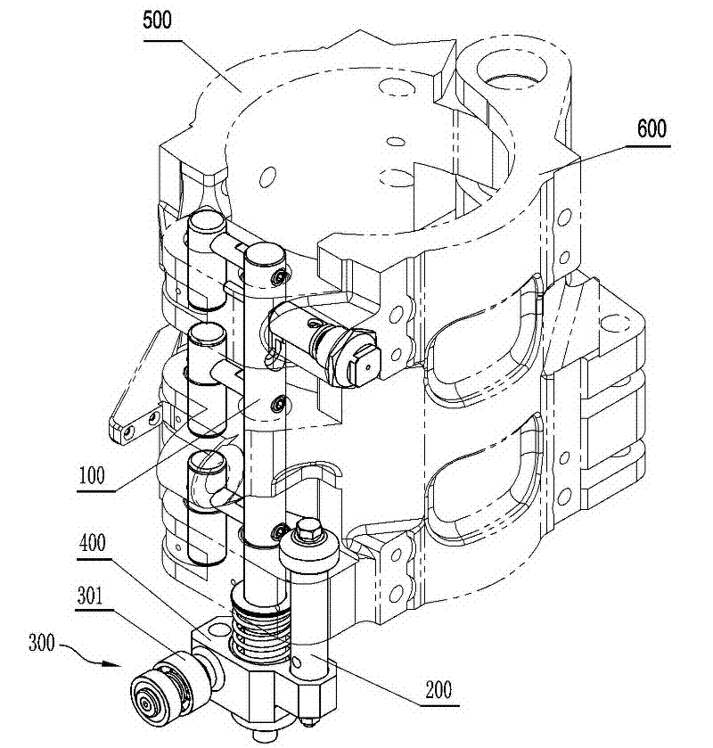
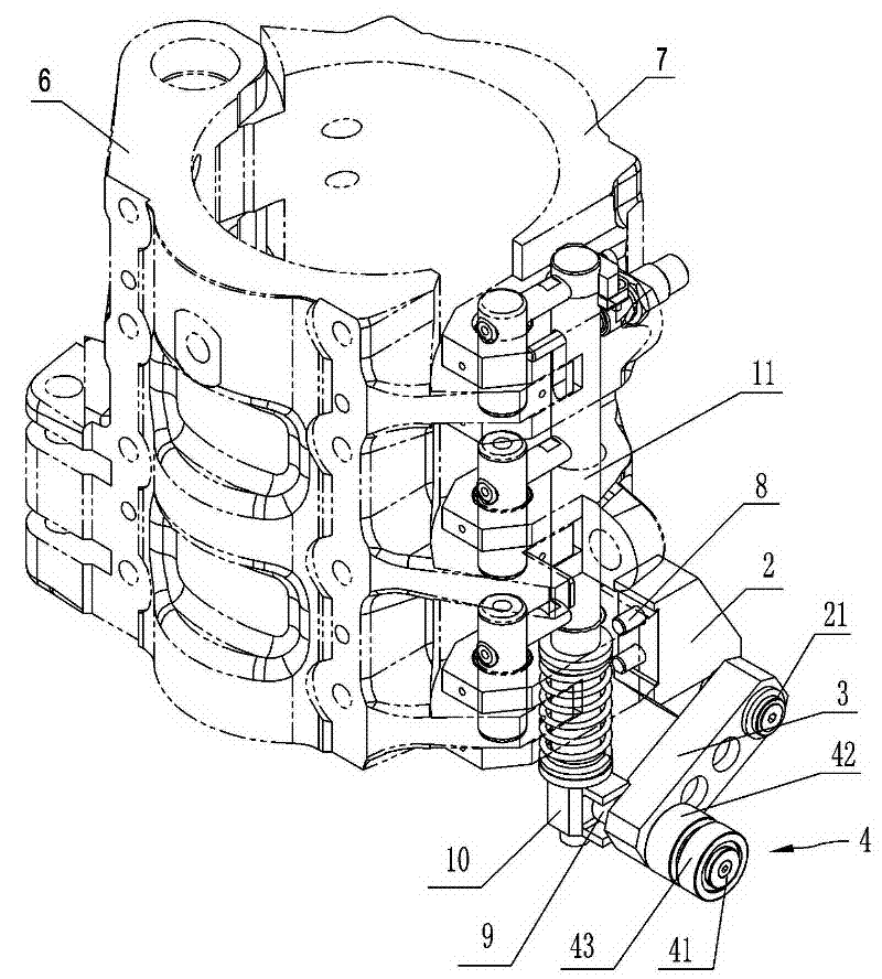
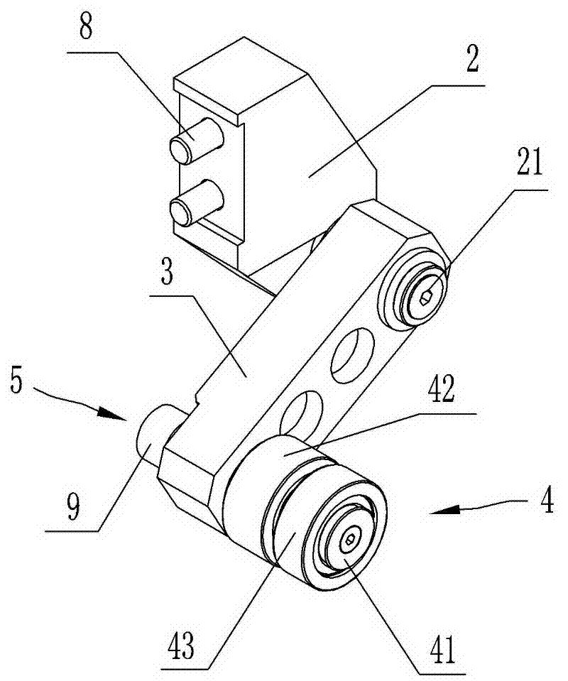
[0012] Such as Figures 2 to 5 As shown, the clamping shaft assembly lift toggle device according to the present invention includes a toggle block 10 fixed at the lower part of the clamping shaft 11 of the clamping shaft assembly 1, and a swing arm member for driving the toggle block 10 up and down , the swing arm component includes a base 2 fixed on the formwork, a swing arm 3 is hinged on the base 2, and a roller assembly 4 is installed on one side of the swing arm 3. This roller assembly 4 is a prior art, and its main Including the roller shaft 41 installed on the swing arm 3, and the first roller 42 and the second roller 43 installed on the roller shaft 41, wherein the first roller 41 is connected with the clamping guide rail (not shown in the figure) on the bottle blowing machine Cooperate, the other side of the swing arm 3 extends the toggle shaft 5, and the opposite surface of the toggle block 10 and the toggle shaft 5 has a slideway 101 for the toggle shaft 5 to stretc...


PUM


Abstract

The invention discloses a mold locking shaft assembly lifting and shifting device, which comprises a shifting block fixed at the lower part of a mold locking shaft, and a swing arm member for driving the shifting block to lift. The swing arm member includes a base fixed on a mold frame, a swing arm hinged on the base, a roller assembly installed at one side of the swing arm, and a shifting shaft extending out from the other side of the swing arm. The face of the shifting block opposite to the shifting shaft is provided with a slideway into which the shifting shaft extends. The invention can make a mold locking mechanism satisfy mold locking requirements of a full-automatic high-speed bottle blowing machine, reduce the failure rate of the bottle blowing machine, greatly reduce the wear probability of the mold locking shaft and prolong the service life of the mold locking shaft.

Description

technical field [0001] The invention relates to a mold locking mechanism, in particular to a lifting and shifting device for a mold locking shaft assembly of the mold locking mechanism. Background technique [0002] The mold base of the bottle blowing machine is equipped with a mold locking mechanism. When working, the mold locking mechanism can make the mold base open or close at the set time, thereby driving the mold on the mold base to open or close together with the mold base to ensure that the bottle The blank can be quickly sent into the cavity of the mold for blow molding, and the finished bottle can be quickly taken out of the cavity of the mold, so frequently repeated. In response to the country's environmental protection call for energy saving, emission reduction and low-carbon economy, the bottle blowing machine has been developed in the direction of full-automatic and high-speed operation in order to improve the utilization rate of energy, and whether the bottle ...

Claims


Application Information

Patent Timeline
Patent Type & Authority Applications(China)
IPC IPC(8): B29C49/56
Inventor 邹大群吴志刚宁远鹏刘玲
Owner GUANGZHOU TECH LONG PACKAGING MACHINERY CO LTD
Why Eureka
Try Eureka