Vertical coil tongs having centering and guiding device

A guiding device and vertical roll technology, applied in the direction of transportation and packaging, load hanging components, etc., can solve the problems of restricting the yield of cold-rolled products, increasing the labor workload of workers, and unfavorable continuous production, so as to achieve great promotion and application value and reduce The labor intensity of workers and the effect of saving raw materials

Inactive Publication Date: 2012-06-20
武钢集团有限公司
View PDF5 Cites 4 Cited by
  • Summary
  • Abstract
  • Description
  • Claims
  • Application Information

AI Technical Summary

Problems solved by technology

In long-term use, it is found that the inner teeth of the vertical coil clamp often damage the coil core and the end face of the steel coil, which causes unnecessary damage to the quality of the steel coil to a certain extent.
According to statistics, the quality damage rate of steel coils caused by vertical coil clamps is about 1 / 1000 every year, which seriously restricts the yield of cold-rolled products and indirectly leads to the increase of production costs. At the same time, the damaged steel coil core needs manual labor. Cutting can be used for normal production, which not only increases the workload of workers, but also consumes time, which is not conducive to the continuous production of the next process

Method used


Image

  • Vertical coil tongs having centering and guiding device
  • Vertical coil tongs having centering and guiding device
  • Vertical coil tongs having centering and guiding device

Examples


Embodiment 1

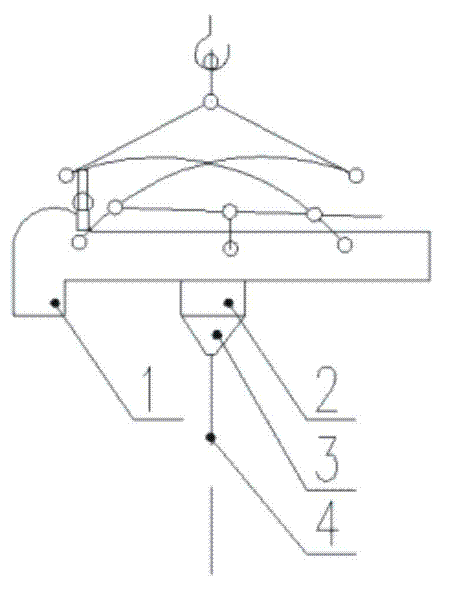
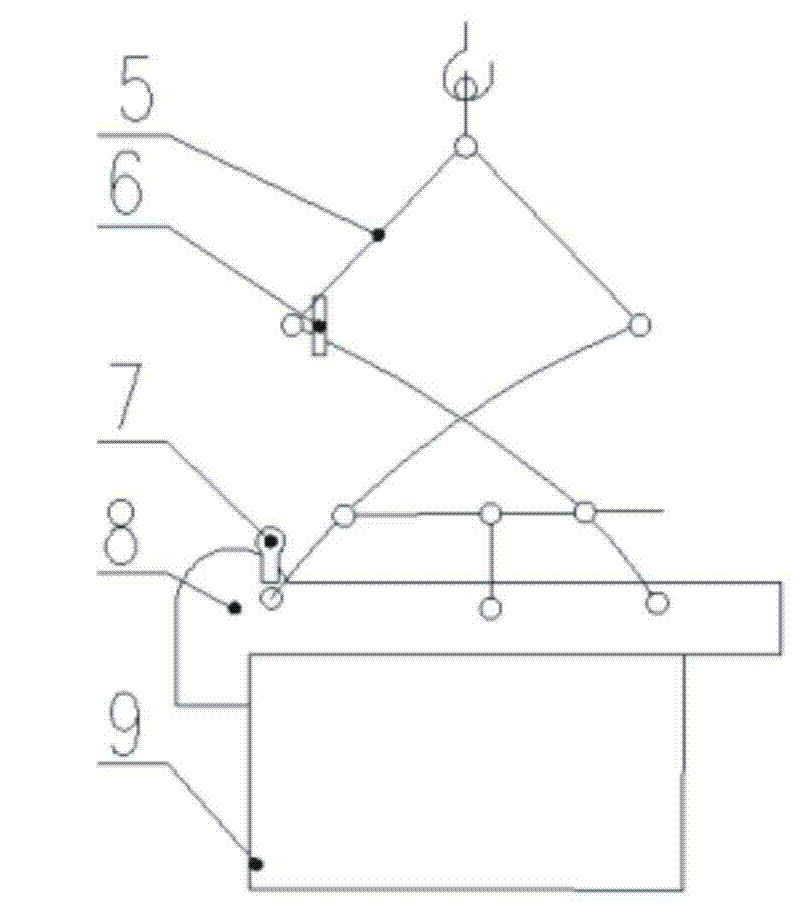
[0025] Example 1, see figure 1 , figure 2 , image 3 , Figure 4 , Figure 5 , Figure 6 , Figure 7 and Figure 8 , a vertical roll tongs with a centering and guiding device, including a pincer arm 8, an outer jaw 1 located at the front end of the pincer arm 8, an inner jaw 2 movably connected to the pincer arm 8, and a control vertical roll clamp Open the tongs or the shutter for clamping the steel coil; the inner jaws 2 are provided with a centering and guiding device 3, and the centering and guiding device 3 includes a guide cylinder 11 with an overall inverted cone shape , the bottom of the guide cylinder 11 is provided with a groove, the groove is provided with a laser mounting seat 16, the laser mounting seat 16 is connected to the groove by threads, the laser emitter 17 is placed in the laser mounting seat 16, and the laser emitter The light beam 4 emitted by 17 coincides with the vertical line of the inner jaw 2; a baffle 15 is provided at the bottom of the l...

Embodiment 2

[0028] Embodiment 2, a vertical roll clamp with a centering and guiding device, including a clamp arm, an outer clamp tooth located at the front end of the clamp arm, an internal clamp tooth that is movably connected to the clamp arm frame, and controls the vertical roll clamp to open A controller for clamping or clamping steel coils; the inner jaws are provided with a centering and guiding device, and the centering and guiding device includes an overall inverted tapered guide cylinder, and the lower part of the guide cylinder There is a groove, and a laser mounting seat is provided in the groove. The laser mounting seat is connected to the groove through threads. The laser emitter is placed in the laser mounting seat, and the beam emitted by the laser emitter is perpendicular to the vertical line of the inner jaw. overlap; a baffle plate is provided on the lower part of the laser mounting seat, and a hole corresponding to the laser transmitter is provided on the baffle plate, ...


PUM


Abstract

The invention relates to vertical coil tongs having a centering and guiding device. The vertical coil tongs comprise a tong arm, an outer tong tooth located at the front end of the tong arm, and an inner tong tooth in movable connection with the tong arm, wherein the inner tong tooth is provided with the centering and guiding device, the centering and guiding device includes an integrally inverted-cone-shaped guide cylinder, a groove is disposed at the lower part of the guide cylinder, a laser emitter is arranged in the groove, and a light beam emitted from the laser emitter is coincident with the perpendicular bisector of the inner tong tooth. The invention has simple structure and convenient use, and can avoid damage to the coil core and the steel coil end face, improve yield, and reduce production costs and labor intensity. In addition, the guide cylinder has a hollow structure inside, which saves raw materials. Advantages of the invention also include simple manufacturing, low cost, convenient installation, strong practicability, and high generalization and application values.

Description

technical field [0001] The invention relates to a vertical roll clamp, in particular to a vertical roll clamp with a centering and guiding device. Background technique [0002] In the bell furnace annealing process, first of all, 3 to 5 or more vertically placed steel coils that need to be annealed must be arranged vertically, and then the furnace cover can be used for annealing. In the process of arranging steel coils, special vertical coil tongs must be used to stack and reverse the steel coils. The vertical coil clamp is a hoisting tool specially used for lifting and transporting the coiled plate in an upright state. The commonly used vertical coil clamp includes a clamp arm, an outer jaw located at the front end of the jaw, and an inner jaw corresponding to the outer jaw. Inlays, and a shutter that controls the vertical coil clamp to open the clamp or clamp the steel coil. In long-term use, it is found that the inner jaws of the vertical coil clamp often damage the co...

Claims


Application Information

Patent Timeline
Patent Type & Authority Applications(China)
IPC IPC(8): B66C1/48B66C1/40
Inventor 袁俊谢建强高云雷汉琴余方杜青黄洪斌付帅
Owner 武钢集团有限公司
Why Eureka
Try Eureka