Vehicle suspension ball head pin assembly

A ball stud and assembly technology, which is applied to vehicle components, steering mechanisms, steering rods, etc., can solve problems such as the inability to ensure the complete positioning of the lower ball bowl, the small swing angle of the ball stud pin, and the difficulty in ensuring the lower ball bowl. Achieve the effects of simple structure, increased swing angle and large swing range

Inactive Publication Date: 2012-06-20
CHINA NORTH VEHICLE RES INST
View PDF4 Cites 8 Cited by
  • Summary
  • Abstract
  • Description
  • Claims
  • Application Information

AI Technical Summary

Problems solved by technology

[0005] Although the two ball studs listed above have their own advantages, there are still two major defects as follows: First, because most ball stud assemblies are only connected to the upper and lower sides by fixing parts such as split lock nuts. The ball bowl is pressed tightly, but there is no structure for positioning the axial direction of the lower bowl. Therefore, when the cross arm moves, it is difficult to ensure that the lower bowl will not rotate around the central axis of the ball head seat, and it is impossible to ensure the alignment of the lower ball. The complete positioning of the bowl; secondly, the lower ball bowl is circular, and the swing angle of the ball stud pin is relatively small. If the cross arm of the vehicle suspension swings up and down a lot, the lower ball bowl may interfere with the ball stud pin

Method used


Image

  • Vehicle suspension ball head pin assembly
  • Vehicle suspension ball head pin assembly
  • Vehicle suspension ball head pin assembly

Examples


Embodiment Construction

[0033] The vehicle suspension ball stud assembly of the present invention will be further described in detail below in conjunction with the accompanying drawings.

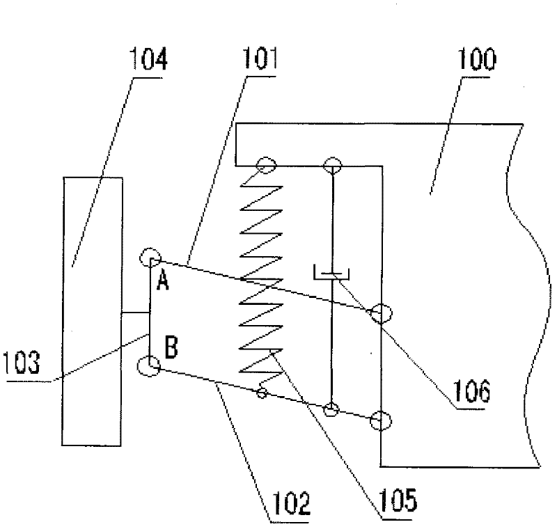
[0034] figure 1 A schematic diagram of the structural principle of the double-wishbone suspension mechanism is shown. like figure 1 As shown, the suspension mechanism is mainly composed of upper cross arm 101, lower cross arm 102, wheel 104, spring 105 and shock absorber 106, and the suspension mechanism forms a four-bar mechanism together with the wheel hub assembly 103 and the car body 100, which is the wheel 104 provides guidance and supports the vehicle body 100 . figure 1 Among them, A and B are the installation positions of the ball stud assembly of the present invention. The present invention connects the joints of the upper and lower cross arms 101, 102 and the hub assembly 103 through the ball stud assembly, and the ball stud is installed at the ends of the upper and lower cross arms 101, 102 through th...


PUM


Abstract

The invention provides a vehicle suspension ball head pin assembly, which comprises a ball head seat fixed on an end of a cross arm, a positioning pin block, a lower ball bowl, a ball head pin, a screw plug, an upper ball bowl, a ball bowl pressing cover and a screw plug. The positioning pin block comprises a positioning block and a cylinder forming a fixed connection on the positioning block. The positioning block of the positioning pin block forms a clamped connection in a positioning groove arranged on the outer surface of the lower ball bowl. The cylinder of the positioning pin block is arranged in a positioning hole arranged on a side wall of the lower part of the ball head seat. The inner surface of the positioning hole is provided with threads for installing the screw plug. The positioning pin block is fixed through the screw plug. According to the vehicle suspension ball head pin assembly of the present invention, the positioning groove is arranged on the outer surface of the lower ball bowl, and is matched with the positioning pin block, such that the rotation of the lower ball bowl around the axial line can be limited; two limit positions on the bottom end of the conicalsurface of the lower ball bowl along the ball head pin movement enveloping surface are respectively cut with a gap structure, such that the panning angle of the ball head pin can be increased, and the vehicle suspension ball head pin assembly of the present invention is especially suitable for off-road vehicles with large suspension travel.

Description

technical field [0001] The invention belongs to the technical field of ball studs, in particular, the invention relates to a vehicle suspension ball stud assembly. Background technique [0002] The upper and lower wishbone of current vehicle double wishbone suspension is connected with the wheel hub by means of ball studs. The ball pin is installed in the ball seat on the cross arm, the ball head is supported and fixed by the upper and lower ball bowls, and the pin rod part is exposed outside the ball seat after passing through the lower ball bowl and the ball seat ; The upper ball bowl is fixed in the mounting hole of the cross arm by the ball bowl gland and the like. [0003] The utility model with authorized notification number CN 201322041Y discloses a ball stud assembly, which includes a ball stud; a ball stud accommodated in the ball stud, the ball stud has a ball head and a pin shaft an outer bush, an inner bush accommodated in the outer bush, the inner bush accommo...

Claims


Application Information

Patent Timeline
Patent Type & Authority Applications(China)
IPC IPC(8): F16C11/06B62D7/18
Inventor 刘广征郭晓燕施睿王东亮汪国胜
Owner CHINA NORTH VEHICLE RES INST
Why Eureka
Try Eureka