Concurrent flow heat exchanger

A technology of parallel flow heat exchangers and flow tubes, applied in evaporators/condensers, lighting and heating equipment, refrigeration components, etc., can solve the problem of deteriorating the flow effect of heat exchangers, reducing the heat transfer effect of heat exchangers, and reducing compression Oil level and other issues, to achieve the effect of simple and reasonable structure, wide application range, and improve heat exchange efficiency

Active Publication Date: 2012-06-20
GD MIDEA AIR-CONDITIONING EQUIP CO LTD
View PDF6 Cites 10 Cited by
  • Summary
  • Abstract
  • Description
  • Claims
  • Application Information

AI Technical Summary

Problems solved by technology

However, this form makes the installation more affected by the structure
In addition, due to the influence of the flat plate structure, when the refrigerant has two phases of gas and liquid, the upper gaseous refrigerant will flow out first, and the gas-liquid two-phase separation will be formed on the side of the flat tube, thereby reducing the heat exchange effect of the heat exchanger
When the heat exchanger is used as a condenser, especially when the condensation temperature is low, more refrigerated oil will be precipitated, and the condensed refrigerated oil will be spread on the upper surface of the equalizer plate, and more refrigerated oil will be collected , reduce the oil level of the compressor, and at the same time deteriorate the flow effect of the heat exchanger

Method used


Image

  • Concurrent flow heat exchanger
  • Concurrent flow heat exchanger
  • Concurrent flow heat exchanger

Examples


no. 1 example

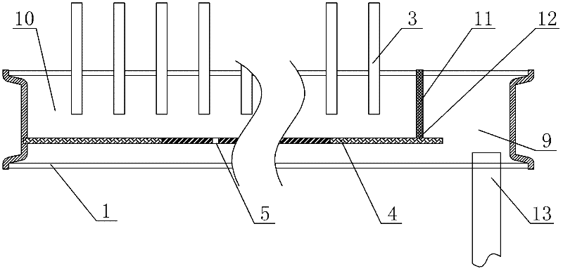
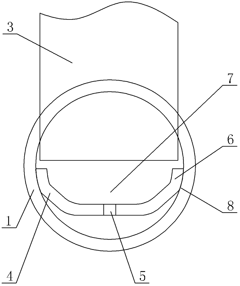
[0027] see Figure 1-Figure 3 . A parallel flow heat exchanger comprising a lower header 1, an upper header 2, several flat tubes 3 arranged between the upper and lower headers, fins arranged between adjacent flat tubes 3, A flow equalizer 4 is arranged inside the lower header 1 , and the flow equalizer 4 divides the lower header 1 into a first cavity 9 connected to the refrigerant pipe 13 and a second cavity 10 connected to the flat tube 3 . The width direction of the flow equalizer 4 is a concave curved surface, and is concave to the lower side of the collector 1 . The wall surface of the concave part of the flow even plate 4 forms a channel 7 with a narrow bottom and a wide top in the second cavity 10 . Specific as figure 2 As shown, a through hole 5 is provided in the concave part of the uniform flow plate 4. When the heat exchanger is used as a condenser, due to the curved surface of the flow uniform plate 4, the refrigerated oil condensed and collected from the flat tu...

no. 2 example

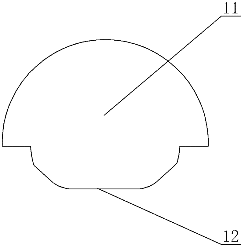
[0032] like Figure 4 , Figure 5 As shown, the shape of the flow equalizer 4 in the width direction of this embodiment is a convex curved surface, and the flow equalizer 5 divides the header 2 into a first cavity 9 connected to the refrigerant pipe 13 and a second cavity 10 connected to the flat tube 3 , the flow equalizer 4 is protruding to the side of the flat tube 3, and a through hole 5 is provided at the place where the flow equalizer 4 is easy to collect oil, that is, at the bend on both sides of the flow equalizer 4 that protrudes to the flat tube 3, specifically as Figure 4 As shown, through holes 5 are provided at the bends on both sides of the flow sharing plate 4 . When the heat exchanger is used as a condenser, due to the curved surface of the flow uniformity plate 4, the refrigerated oil condensed and collected from the flat tubes 3 will be collected in the lower part of the channel 7, so as to flow into the lower side of the flow uniformity plate 4 through the...

no. 3 example

[0037] see Image 6, The main difference between this parallel flow heat exchanger and the second embodiment is that two rows of through holes 5 are arranged alternately along the direction of the axis of the lower header 1 on the curved surfaces on both sides of the flow equalizer 4 . In this way, the distance between the through holes 5 in each row can be enlarged, the total number of holes can be reduced, and the speed of the refrigerant flowing out from the through holes 5 can be increased, thereby further increasing the uniformity of gas-liquid mixing and improving the heat exchange efficiency of the heat exchanger. Other unmentioned parts are the same as the second embodiment.


PUM


Abstract

The invention discloses a concurrent flow heat exchanger which comprises a lower flow collecting pipe, an upper flow collecting pipe, a plurality of flat pipes arranged between the upper flow collecting pipe and the lower flow collecting pipe and fins arranged between the adjacent flat pipes, wherein the lower flow collecting pipe is internally provided with a flow equalization plate; the width direction of the flow equalization plate is of a convex-concave curved surface or a cambered surface; the part, at which oil is easy to collect, of the flow equalization is provided with a through hole; and the lower flow collecting pipe is divided into a first cavity connected with a refrigerant pipe and a second cavity connected with the flat pipes by the flow equalization plate. According to the invention, the refrigerant enters the larger cavity from the smaller cavity through the through hole on the flow equalization plate, because the flow path of the refrigerant is expanded, refrigerants of gas and liquid phases can be mixed fully, and the heat exchange efficiency of the heat exchanger is improved; when the concurrent flow heat exchanger acts as a condenser, because of the curved surface of the flow equalization plate in width direction, refrigeration oil collected from the flat pipes through condensation is collected to the lower part of the path, and flows back to a refrigerant system through the through hole on the flow equalization plate, thus the flow of the refrigerant is influenced, and the hold-up volume of the refrigeration oil is reduced; and the concurrent flow heat exchanger has the characteristics of simple and reasonable structure, high heat exchange efficiency and wide application range.

Description

technical field [0001] The invention relates to a parallel flow heat exchanger. Background technique [0002] As a high-efficiency heat exchanger, the parallel flow heat exchanger is used in more and more fields. However, in order to improve the flow equalization of the refrigerant in ordinary parallel flow heat exchangers, a refrigerant equalizer plate is installed in the liquid side header. , to communicate with the two cavities separated by the equalizing plate. However, this form makes the installation more affected by the structure. In addition, due to the influence of the flat plate structure, when the refrigerant has two phases of gas and liquid, the upper gaseous refrigerant will flow out first, and the gas-liquid two-phase separation will be formed on the side of the flat tube, thereby reducing the heat exchange effect of the heat exchanger. When the heat exchanger is used as a condenser, especially when the condensation temperature is low, more refrigerating oil...

Claims


Application Information

Patent Timeline
Patent Type & Authority Applications(China)
IPC IPC(8): F25B39/00
Inventor 刘阳李强佐藤宪一郎
Owner GD MIDEA AIR-CONDITIONING EQUIP CO LTD
Why Eureka
Try Eureka