
Method for realizing pulse check through digital circuit

A digital circuit and pulse technology, which is applied in the field of power electronic IGBT applications, can solve the problems such as the inability to realize the protection function in a targeted manner, and achieve the effects of good protection, realization of protection, and prevention of false and false alarms.

Active Publication Date: 2012-06-20
天威新能源系统工程(北京)有限公司
View PDF4 Cites 4 Cited by
  • Summary
  • Abstract
  • Description
  • Claims
  • Application Information

AI Technical Summary

Problems solved by technology

In the background technology, some manufacturers have introduced corresponding IGBT drive circuits and drive boards, but only provide matching and transmission of trigger and protection signals for IGBTs, and cannot achieve corresponding protection functions in a targeted manner.

Method used


Image

  • Method for realizing pulse check through digital circuit
  • Method for realizing pulse check through digital circuit
  • Method for realizing pulse check through digital circuit

Examples


Embodiment Construction

[0016] The present invention will be further described through the embodiments below in conjunction with the accompanying drawings.

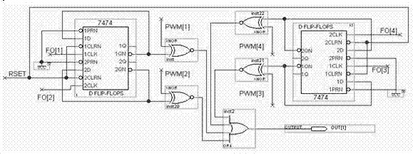
[0017] A method for realizing pulse verification through a digital circuit, including the following steps: ①The pulse signal returned by the IGBT is divided by the D flip-flop and compared with the original pulse, and the compared signal is passed through the OR gate together with the power failure signal SO sent by the IGBT Finally, a series of 220ns short pulses are output; ②A series of short pulses undergo subsequent processing, and the part from the rising edge to about 220-250ns of this series of pulses is removed, so that the delayed signal generated by the pulse comparison is removed, and the remaining signal is widened Processing, the widening width is determined by the number of external CLK and triggers; ③If there is no FO alarm or SO alarm after the signal is processed, a low-level "zero" signal will be output; if there is a FO or SO s...


PUM


Abstract

The invention relates to a method for realizing pulse check through a digital circuit, which belongs to the technical field of IGBT (insulated gate bipolar transistor) applications of power electronics. The technical scheme comprises the following steps of: (1) performing frequency division on a pulse signal returned by an IGBT via a D trigger, then comparing the pulse signal with an original pulse, enabling the signal after comparison and a power supply fault signal SO emitted by the IGBT to pass through an or gate and then outputting a series of 220ns short pulses; (2) removing the part from a rising edge to about 220-250nm from the series of the pulses to remove a time delay signal generated by pulse comparison, and performing broadening treatment on the remaining signal, wherein the broadening width is decided by the number of external CLK (clocks) and triggers; and (3) finally outputting a low-level zero signal if an FO (fiber optic) alarm or an SO alarm does not exist; and outputting the pulse signal decided by the number of CLK signals and the triggers if an FO or SO signal exists. According to the method disclosed by the invention, logic conversion and digital pulse signalprocessing are realized in a hardware circuit way, the reliability is high, the anti-interference ability is strong, the original protection function is reinforced and extended, and the protection ofthe IGBT can be better realized.

Description

technical field [0001] The invention relates to a method for realizing pulse verification through a digital circuit, relates to the processing and transmission of protection signals, error signals and pulse signals in the driving and triggering process of a power device IGBT, and belongs to the technical field of power electronic IGBT applications. Background technique [0002] With the rapid development of power electronics technology, IGBT (Insulated Gate Bipolar Transistor) is a new type of power electronic device that came out in the mid-1980s. It combines the fast response of MOSFET, high input impedance and low on-state of GTR. Many excellent characteristics such as voltage drop and high current density have been developed rapidly, and they can replace almost all other types of power devices so far. The existing mature high-voltage grade IGBT has reached 4000V, and the high-frequency IGBT has reached 150K hard switching and other high performance. The application rang...

Claims


Application Information

Patent Timeline
Patent Type & Authority Applications(China)
IPC IPC(8): G01R31/26
Inventor 王文瑞包凤永张喜军任晓鹏高姊敬王飞
Owner 天威新能源系统工程(北京)有限公司
Learn More