Method for testing error influence quantity to high-voltage three-phase current transformer from high-voltage leakage current

A technology of current transformer and three-phase current is applied in the field of testing the influence of high-voltage leakage current on the error of high-voltage three-phase current transformer, which can solve the problem that it is difficult to accurately measure its size, small resistance, and high AC RMS voltmeter. It is difficult to accurately measure and other problems, so as to improve the efficiency of detection work, improve the accuracy, improve the accuracy and the efficiency of measurement work.

Inactive Publication Date: 2012-06-20
STATE GRID SICHUAN ELECTRIC POWER CORP ELECTRIC POWER RES INST +1
View PDF5 Cites 7 Cited by
  • Summary
  • Abstract
  • Description
  • Claims
  • Application Information

AI Technical Summary

Problems solved by technology

The resistance given in JJG 1021-2007 is the rated load resistance, so the resistance is too small, and the voltage at both ends is about 1mV, which is difficult to measure accurately with an AC rms voltmeter
JB / T 10432-2004 recommends 100Ω or 5Ω, so that when the leakage current is 1mA, the voltage can reach about 10mV, but it is difficult to accurately measure its size with an ordinary AC RMS voltmeter
At the same time, the above method cannot directly measure the influence of the leakage current on the actual error of the current transformer in the high-voltage three-phase combined transformer under the influence of the three-phase voltage.

Method used


Image

  • Method for testing error influence quantity to high-voltage three-phase current transformer from high-voltage leakage current
  • Method for testing error influence quantity to high-voltage three-phase current transformer from high-voltage leakage current
  • Method for testing error influence quantity to high-voltage three-phase current transformer from high-voltage leakage current

Examples


Embodiment Construction

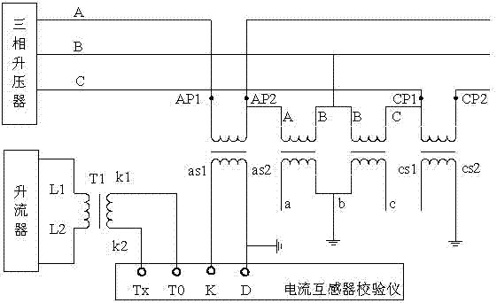
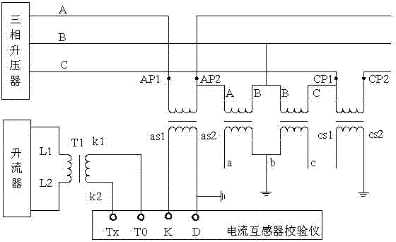
[0020] Explanation of the signs in the attached drawings: figure 1 Among them, T0 and Tx are the working current input terminals of the current transformer calibrator, and K and D are the differential current (ie small current) inputs of the current transformer calibrator. T1 is the current transformer for testing. AP1 and AP2 are the primary polarity and non-polarity terminals of the A-phase current transformer in the high-voltage three-phase transformer, and CP1 and CP2 are the primary polarity and non-polarity terminals of the C-phase current transformer in the high-voltage three-phase transformer. as1 and as2 are the secondary polarity and non-polarity terminals of the A-phase current transformer in the high-voltage three-phase transformer, and cs1 and cs2 are the secondary polarity and non-polarity terminals of the C-phase current transformer in the high-voltage three-phase transformer end.

[0021] figure 1 It shows that during the measurement, the three-phase booster...


PUM


Abstract

The invention discloses a method for testing error influence quantity to a high-voltage three-phase current transformer from high voltage leakage current, which comprises the following steps of adopting a booster to implement three-phase symmetric rated voltage on a primary terminal of the high-voltage three-phase current transformer, inputing the leakage current output by a secondary terminal of the current transformer into a transformer calibrator as differential current, and inputing one percent rated current of the secondary output of the tested current transformer which is generated by the booster and the current transformer for test into the transformer calibrator as working current, so that the transformer calibrator can directly measure the error influence quantity of the high-voltage leakage current to the high-voltage three-phase current transformer at the one percent rated current point. The phase position of the working current of the transformer calibrator is in accordance with the phase position of the voltage implemented by the primary terminal of the tested current transformer, so that the operation performance of the high-voltage three-phase current transformer under an actual operation condition is truly realized; and the accuracy of the test results and test efficiency are improved.

Description

technical field [0001] The invention relates to a new test method for the influence of high-voltage leakage current on the error of a high-voltage current transformer, which is suitable for direct testing of the influence of leakage current on the error of a current transformer in a high-voltage state, and is especially suitable for the influence of high-voltage leakage current on the error of a high-voltage three-dimensional transformer. A direct test method for the influence of phase current transformer errors. Background technique [0002] If a high voltage is applied to the primary winding of a high voltage current transformer, the high voltage will generate a capacitive current flowing from the primary winding to the secondary winding (when the secondary winding has no shielding measures), and part of this current flows through the secondary winding connected to the transformer. Secondary equipment, some flow directly to the ground terminal of the secondary winding, so ...

Claims


Application Information

Patent Timeline
Patent Type & Authority Applications(China)
IPC IPC(8): G01R35/02
CPCG01R35/02G01R31/027G01R31/62
Inventor 杨华云江波艾兵刘刚杨勇波
Owner STATE GRID SICHUAN ELECTRIC POWER CORP ELECTRIC POWER RES INST
Why Eureka
Try Eureka