

Method for limiting secondary arc current for untransposed transmission line with extra-high voltage
A transmission line and submerged current technology, which is applied in the direction of emergency protection circuit devices, circuit devices, emergency protection circuit devices, etc. for limiting overcurrent/overvoltage, and can solve the problem of large submerged current of UHV non-transposition lines. problems, to achieve the effect of increasing the difficulty of manufacturing
- Summary
- Abstract
- Description
- Claims
- Application Information
AI Technical Summary
Problems solved by technology
Method used
Image

Examples
Embodiment Construction
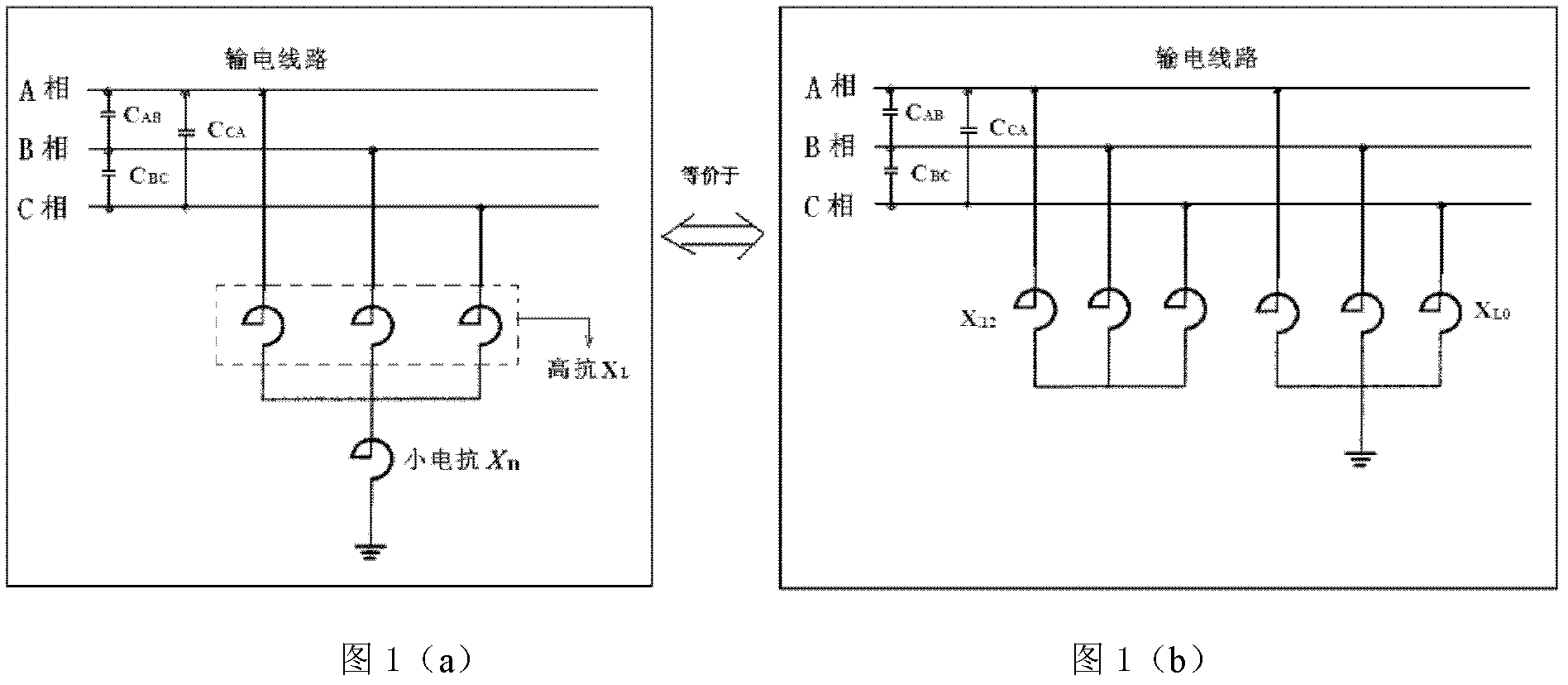
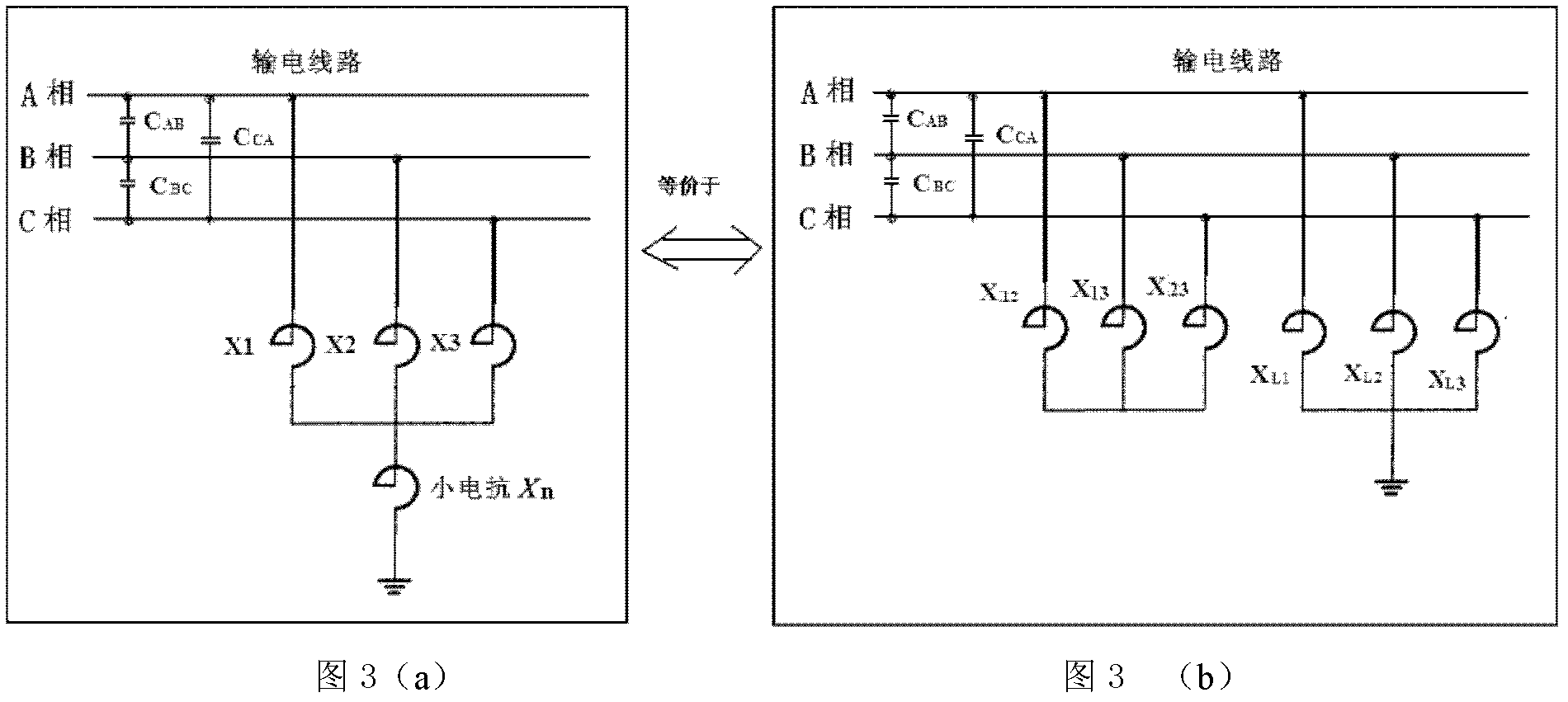
[0020] Three-phase unbalanced high reactance plus small reactance is used to limit the submerged current of the non-transposition UHV line, and its wiring method adopts three-phase unequal high reactance at its neutral point and small reactance for grounding, as shown in Figure 3(a) Show.
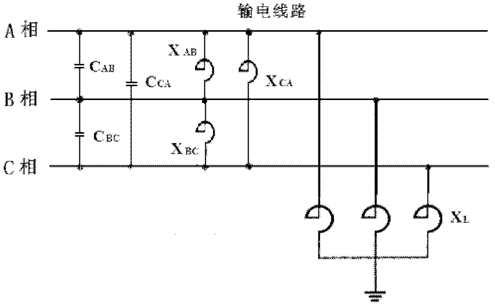
[0021] Due to the distance between the three-phase wires (in l AB , l BC , l CA Indicates) are not equal, taking the horizontal arrangement of conductors as an example, l AB = l BC ≠l CA , then the phase-to-phase capacitance of the wires is not equal, that is, C in Figure 3(a) AB =C BC ≠C CA . To compensate for phase-to-phase capacitance, the relationship between phase-to-phase reactance in parallel with capacitance is X 12 =X 23 ≠X 13 , as shown in Figure 3(b). Reactance X in Figure 3(b) L1 、X L2 、X L3 Compensate the ground capacitance of the A-phase, B-phase and C-phase lines respectively; convert Figure 3(b) into Figure 3(a) equivalently. In this way, the solution of thre...
PUM
 Abstract
Description
Claims
Application Information