Motor rotor

A motor rotor and cogging technology is applied in the field of motor rotors with embedded permanent magnets, which can solve the problems of low torque control accuracy and high torque ripple, improve torque control accuracy, improve field weakening characteristics, reduce Effect of torque ripple

Active Publication Date: 2012-06-20
SUZHOU DRANE ELECTRIC MOTORS
View PDF9 Cites 11 Cited by
  • Summary
  • Abstract
  • Description
  • Claims
  • Application Information

AI Technical Summary

Problems solved by technology

This technical solution solves the problem of fixing the permanent magnet well, but it still has the following disadvantages: the torque ripple is high at low speed, and the torque control accuracy is low

Method used


Image

  • Motor rotor
  • Motor rotor
  • Motor rotor

Examples


Embodiment Construction

[0021] The purpose of the present invention is to provide a motor rotor with small torque ripple and high torque control precision.

[0022] The technical solutions in the embodiments of the present invention will be described in detail below in conjunction with the accompanying drawings in the embodiments of the present invention. Obviously, the described embodiments are only some of the embodiments of the present invention, not all of them. Based on the embodiments of the present invention, all other embodiments obtained by persons of ordinary skill in the art without making creative efforts belong to the protection scope of the present invention.

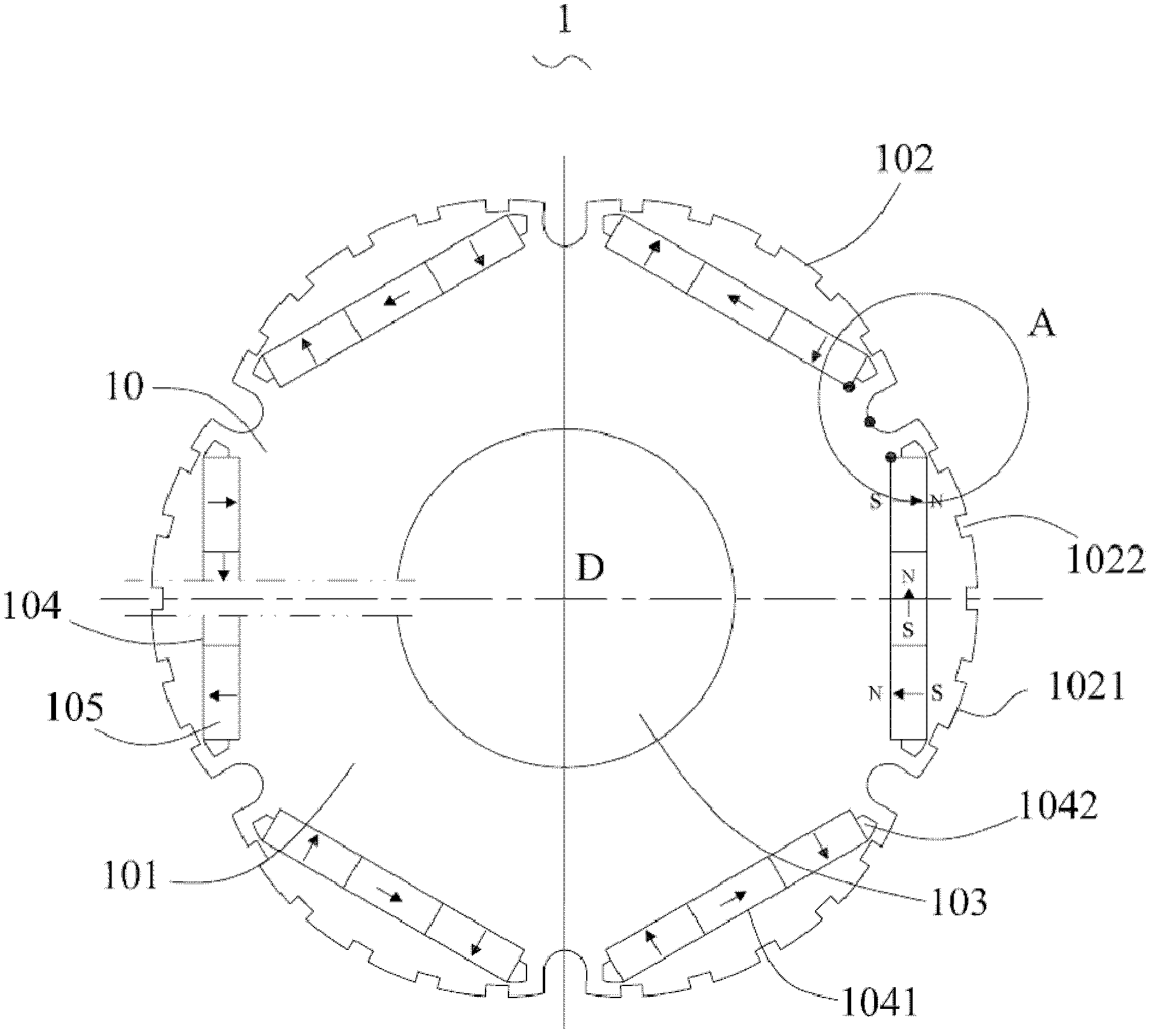
[0023] ginseng figure 1 As shown, in the specific embodiment of the present invention, the motor rotor 1 is suitable for an electric motor, and the motor also includes a stator (not shown in the figure), and the stator is contained on the outside of the motor rotor 1 .

[0024] The motor rotor 1 has a main axis of rotation D, wh...


PUM


Abstract

The invention discloses a motor rotor. The motor rotor comprises permanent magnets, is provided with a main axis and further comprises an iron core, wherein the iron core is defined by an end wall and a lateral surface, and provided with a hole for being connected to the shaft of a motor and a plurality of longitudinal grooves for being mounted in the permanent magnets; and tooth grooves are formed on the lateral surface along the main axis. According to the invention, as the tooth grooves are formed on the outer surface of the motor rotor, the cogging force of the motor is reduced by the structure, torque pulsation is reduced, the torque control precision is improved, and meanwhile, the motor has better flux-weakening property and can run at high speed.

Description

technical field [0001] The invention relates to a motor rotor, in particular to a motor rotor embedded with permanent magnets. Background technique [0002] Like the driving motor used in electric vehicles, it is required that the motor can provide a large torque at low speed, and it must not only meet the high-speed operation requirements at high speed, but also continue to provide large torque, which brings great challenges to the design and manufacture of the motor. A lot of questions came up. [0003] In 1973, American scholar Mallianson discovered a peculiar permanent magnet structure during an assembly experiment on the permanent magnet structure, and called it "Magnetic Curiosity". He did not realize the application value of this structure at that time. In 1979, American scholar Klaus Halbach discovered this special permanent magnet structure when he used the magnetic field generated by various permanent magnet structures to do electron acceleration experiments, and...

Claims


Application Information

Patent Timeline
Patent Type & Authority Applications(China)
IPC IPC(8): H02K1/27H02K1/28
Inventor 刘吉柱黄海波陈涛潘明强王蓬勃范立成
Owner SUZHOU DRANE ELECTRIC MOTORS
Why Eureka
Try Eureka