Supercharge Your Innovation With Domain-Expert AI Agents!

Switching system and equipment system

A technology for switching systems and equipment, applied in the field of buses, can solve problems such as single bus connection, achieve flexible and variable connection methods, and realize serial or parallel conversion.

Inactive Publication Date: 2012-06-20
SOUTH CHINA UNIV OF TECH
View PDF4 Cites 3 Cited by
  • Summary
  • Abstract
  • Description
  • Claims
  • Application Information

AI Technical Summary

Problems solved by technology

[0004] As mentioned above, the existing lighting systems are all connected by a single bus, that is, either serial connection or parallel connection, and no matter whether it is a parallel connection lighting system or a serial connection lighting system, it cannot Avoid the pitfalls, therefore, it is urgent to find a new bus topology for the system

Method used


Image

  • Switching system and equipment system
  • Switching system and equipment system
  • Switching system and equipment system

Examples


Embodiment Construction

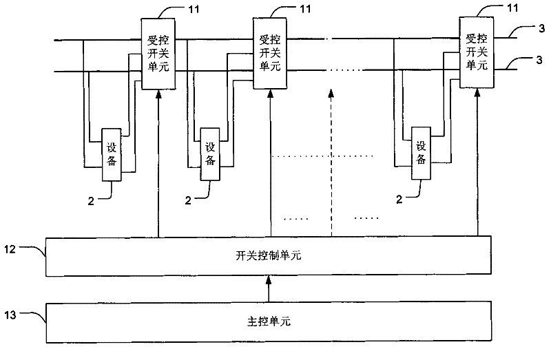
[0015] see image 3 , the switching system for switching bus connection modes of the present invention is applied to a plurality of devices 2 connected to the bus 3 . Preferably, said device 2 comprises a lamp.

[0016] The switching system includes: a plurality of controlled switch units 11 , at least one switch control unit 12 and a main control unit 13 .

[0017] Each controlled switch unit 11 is respectively connected to a device 2 and the bus 3 . For example, if image 3 As shown, the first controlled switch unit 11 is connected to the first device 2 and the bus 3, the second controlled switch unit 11 is connected to the second device 2 and the bus 3, ... the last controlled switch unit 11 The control switch unit 11 is connected with the last device 2 and the bus 3.

[0018] Preferably, each controlled switch unit 11 includes two controlled switches, for example, as Figure 4 As shown, each controlled switch unit 11 includes two controlled switches, and each controll...


PUM


Abstract

The invention provides a switching system and an equipment system. The switching system is used for connecting multiple equipments connected with a bus, and comprises a plurality of controlled switch units, at least one switch control unit and a master control unit, wherein each of the plurality of controlled switch units is connected with a piece of equipment and the bus; the at least one switch control unit is connected with the controlled end of each controlled switch unit and is used for controlling the on-off of the plurality of controlled switch units; the master control unit is connected with each switch control unit and is used for outputting on and off signals, so that each switch control unit is led to control the corresponding controlled switch unit to carry out the on-off operations, furthermore, the equipment connected with the controlled switch unit is led to be connected with the adjacent equipments in series or parallel; and based on the switching system, the equipment system with flexible and alterable connection modes can be formed, therefore, the problems in the existing equipment system with simplex connection mode can be effectively avoided.

Description

technical field [0001] The invention belongs to the field of buses, in particular to a switching system and a device system. Background technique [0002] With the overcoming of the bottleneck of LED technology, the market scale of LED lighting applications has maintained a sustained and rapid growth, among which the application of LED lamps in architectural lighting is the most anticipated. In architectural landscape lighting, LED lamps are mainly used in architectural decoration, interior decoration, tourist attraction decoration, etc. In addition, LED lamps are also used for decorative lighting of important buildings, commercial centers, places of interest, bridges, homes, leisure and entertainment places, And commercial lighting integrating decoration and advertising. [0003] At present, there are mainly two types of topologies for LED lighting systems on the market. One is a parallel luminaire system where luminaires are connected in parallel, such as figure 1 shown...

Claims


Application Information

Patent Timeline
IPC IPC(8): H05B37/02
Inventor 王前李韬
Owner SOUTH CHINA UNIV OF TECH
Features
  • R&D
  • Intellectual Property
  • Life Sciences
  • Materials
  • Tech Scout
  • Unparalleled Data Quality
  • Higher Quality Content
  • 60% Fewer Hallucinations
Learn More