Rolling mill guide mechanism

A technology of rolling mill and guiding device, applied in the direction of guiding/positioning/aligning device, etc., can solve the problems of unsatisfactory material rolling effect, inability to solve the problems such as rolling material running, increased raw material consumption, etc., so as to shorten the product delivery time, reduce rolling The effect of ideal control and profit maximization

Active Publication Date: 2012-06-27
浙江富日进精密金属股份有限公司
View PDF4 Cites 6 Cited by
  • Summary
  • Abstract
  • Description
  • Claims
  • Application Information

AI Technical Summary

Problems solved by technology

Its shortcoming: it cannot solve the rolling material running situation
[0003] The rolling mill used in the workshop is not equipped with a guide mechanism, so when the material is rolled, it is easy to cause the material to deviate or even slip, which leads to the unsatisfactory rolling effect of the material, which greatly reduces the yield and brings great impact on the production process. After the rolling of a coil of strip steel is completed, the rolling mill will cut off the steel strip on one side and place it on the track of the rolling mill. The tail of the finished steel strip is not guided, so the final rolling of the rolling mill is not in place, so that this section of material Scrapped. At the same time, when the head of the unrolled material placed on the rolling mill track is put into the next rolling, it needs to be directly connected to the steel coil and cannot be rolled, resulting in the need to discard this section of material. This form of production is extremely wasteful of resources. , so that the consumption of raw materials is greatly increased, and the material wasted as much as 150 tons in the year

Method used


Image

  • Rolling mill guide mechanism
  • Rolling mill guide mechanism

Examples


Embodiment 1

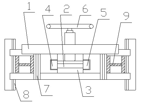
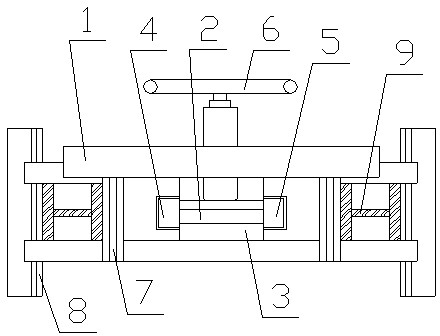
[0009] Embodiment 1: with reference to attached figure 1 , a rolling mill guide mechanism, which includes a frame 1, upper and lower clamping plates 2 and 3, left and right guides 4 and 5, the upper and lower clamping plates 2 and 3 are arranged on the frame 1 Between the upper and lower beams of the frame, the left and right guides 4 and 5 are installed on both sides of the upper and lower clamping plates 2 and 3, and the upper and lower guide adjustment devices 6 are installed on the upper beam of the frame 1, and the upper and lower guides are adjusted The adjusting rod at the bottom of the device 6 passes through the upper crossbeam and is connected with the upper clamping plate 2, and the upper and lower clamping plates 2 and 3 are connected with the left and right guides 4 and 5 to be provided with a locking plate. Both ends of the upper and lower beams are provided with openings for inserting plates, which are used to install quick inserting plates 7. Positioning guide ...


PUM


Abstract

The invention relates to a rolling mill guide mechanism with the advantages that the combined fixation mode is adopted, the material position guide can be realized, the finished product rate of materials can be greatly improved, the waste of strip heads and strip tails of the materials is also reduced, and a large number of raw materials are saved. The rolling mill guide mechanism comprises a machine frame, wherein an upper clamping plate and a lower clamping plate are arranged between an upper cross beam and a lower cross beam of the machine frame, a left guide device and a right guide device are arranged at two sides of the upper clamping and the lower clamping plate, the upper cross beam of the machine is provided with a vertical position guide regulator, in addition, a regulating rod arranged at the bottom of the vertical position guide regulator passes through the upper cross beam to be connected with the upper clamping plate, and parts of the upper clamping plate and the lower clamping plate connected with the left guide device and the right guide device are provided with locking plates. The rolling mill guide mechanism has the advantages that 1, a position guide mechanism is applicable to the position guide of materials with different thicknesses, and in addition, the condition of vertical material jumping caused by the shaking generated during the rolling mill operation is avoided; and 2, the position guide mechanism is adopted, the tail parts of finished steel strips and the head parts of non-rolled materials are ensured to pass through a rolling mill for rolling, and the waste of raw materials is reduced.

Description

technical field [0001] The invention relates to a rolling mill guiding mechanism which adopts a combined fixing method and can be used for guiding the material, which can not only greatly increase the yield of the material, but also reduce the waste of the material head and tail, and save a large amount of raw materials. It belongs to the auxiliary rolling mill Equipment manufacturing field. Background technique [0002] CN201862641U, name " front guide guard mechanism of active rolling mill ", described front guide guard mechanism comprises: bracket, the position guide body that is arranged on the bracket, a pair of front guide guard rolls, a pair of rear guide guard rolls; A pair of front guide guard rolls and A pair of rear guide rollers have the same structure and are respectively arranged symmetrically at the front and rear ends of the guide body; both the front guide roller and the rear guide roller are provided with a gap adjustment device for changing the gap between...

Claims


Application Information

Patent Timeline
Patent Type & Authority Applications(China)
IPC IPC(8): B21B39/16
Inventor 张会晓
Owner 浙江富日进精密金属股份有限公司
Why Eureka
Try Eureka