Adjustable multishaft screwing mechanism

A technology of tightening machine and adjustment mechanism, applied in metal processing, metal processing equipment, manufacturing tools, etc., can solve the problems of inconvenience, small adjustment range, low assembly efficiency, etc., to ensure assembly quality and performance, and ensure accurate alignment. 、Accurate effect of tightening process

Inactive Publication Date: 2012-06-27
AIR FORCE UNIV PLA
View PDF5 Cites 10 Cited by
  • Summary
  • Abstract
  • Description
  • Claims
  • Application Information

AI Technical Summary

Problems solved by technology

[0003] The single-axis tightening machine is operated by workers, and the alignment of the tightening head, the magnitude of the torque, and the tightening sequence are all controlled by humans. Errors and leaks are inevitable, and precise control cannot be achieved to ensure assembly quality and performance.
When the number of bolts is large, the assembly efficiency is low and the labor intensity of workers is high
The position of the tightening head of the multi-axis tightening machine is mostly fixed, and the purpose is single. Once the bolt position changes during the assembly process, it is necessary to re-purchase the multi-axis tightening equipment, and the price of the multi-axis tightening equipment is generally relatively high, which will greatly increase the cost. necessary waste
For a small number of multi-axis tightening equipment, although it can be adjusted, the adjustment range is small, or only the distance or angle can be adjusted, and the self-adjustment structure is complicated, the manufacturing cost is high, and the fabrication is inconvenient, and the precise adjustment of angle and distance cannot be realized.

Method used


Image

  • Adjustable multishaft screwing mechanism
  • Adjustable multishaft screwing mechanism
  • Adjustable multishaft screwing mechanism

Examples


Embodiment Construction

[0030] The mechanism of the present invention will be further described in detail below in conjunction with the description of the drawings and specific embodiments.

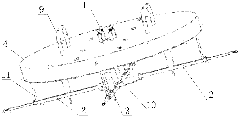
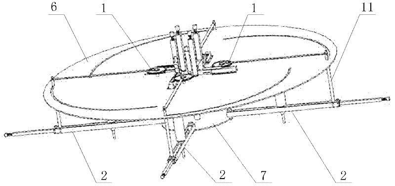
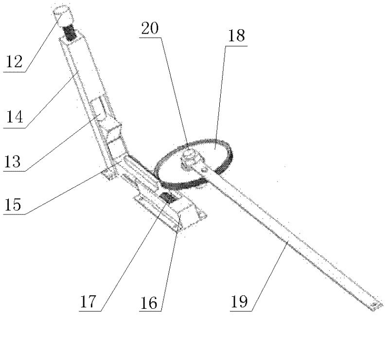
[0031] figure 1 , figure 2 Respectively represent the whole body of the adjustable multi-axis tightening machine of the present invention and the structural schematic diagram after removing the top cover, image 3 , Figure 7 Respectively represent the structures of the angle adjustment mechanism and the radial adjustment mechanism in the present invention, Figure 4 , Figure 5 , Figure 6 Respectively represent the structures of the upper carriage, the upper sliding bar, and the rotating sliding shaft in the angle adjustment mechanism, Figure 8 , Figure 9 Respectively represent the mechanism of the lower frame and the lower sliding bar in the radial adjustment mechanism, Figure 10 Represented the structure of the uniaxial tightening machine in the present invention, Figure 11 The structure of the ...


PUM


Abstract

The invention discloses an adjustable multishaft screwing mechanism, which comprises angle adjusting mechanisms, radial adjusting mechanisms, single-shaft screwing machines, a frame and a driving control unit, wherein the angle adjusting mechanisms are fixed on the upper disc of the frame, the radial adjusting mechanisms are installed on a lower disc, adjusting link rods are used for connecting the angle adjusting mechanisms with the corresponding radial adjusting mechanisms, the single-shaft screwing machines are installed on the radial adjusting mechanisms, and the driving control unit is installed on the top cover of the frame. By adopting the invention, the screwing speeds, moments and directions of different single-shaft screwing machines are controlled; and the adjustable multishaft screwing mechanism disclosed by the invention has the advantages of high regulation precision, simple structure, convenience for adjusting and the like, and can realize rapid screwing of bolts at different positions.

Description

technical field [0001] The invention relates to a multi-axis bolt tightening device, in particular to a multi-axis tightening mechanism capable of accurately adjusting the orientation of a tightening head. Background technique [0002] In order to ensure the assembly quality and overall performance of high-precision equipment, it is necessary to accurately control the torque and tightening sequence of important bolts and nuts during the assembly process. However, the traditional manual tightening method is very random, and it is difficult to accurately tighten the tightening process. controlled and inefficient. For this reason, a large number of single-spindle tightening machines and multi-spindle tightening machines are used in the assembly process. [0003] The single-axis tightening machine is operated by workers, and the alignment of the tightening head, the magnitude of the torque, and the tightening sequence are all controlled by humans. Errors and leaks are inevitabl...

Claims


Application Information

Patent Timeline
Patent Type & Authority Applications(China)
IPC IPC(8): B23P19/06
Inventor 王崴赵杰李培林刘晓卫许晓东炊明伟肖强明
Owner AIR FORCE UNIV PLA
Why Eureka
Try Eureka