Device and method for mounting valve seat

A valve seat and hand technology, applied to hand-held tools, manufacturing tools, etc., can solve the problems of increased operation risk, increased hoisting operation, no benefit, etc., to achieve the effect of convenient operation, avoid hoisting operation, and save man-hours

Inactive Publication Date: 2012-06-27
HUDONG HEAVY MACHINERY
View PDF7 Cites 1 Cited by
  • Summary
  • Abstract
  • Description
  • Claims
  • Application Information

AI Technical Summary

Problems solved by technology

However, limited to the structure of the hydraulic press itself, in order to install the valve seat, the cylinder head needs to be hoisted to the operating platform of the hydraulic press, which not only increases a lot of hoisting operations, but also increases the risk of operation
According to the old process of installing the PC26 cylinder head intake valve seat, the cylinder head needs to be hoisted to the workbench of the hydraulic press first. This is the most time-consuming step, but obviously this step does not produce actual benefits and increases the risk.
At the same time, in order to move the cylinder head to ensure that the intake valve seat is aligned with the head of the hydraulic press, it is also inconvenient on the workbench

Method used


Image

  • Device and method for mounting valve seat
  • Device and method for mounting valve seat
  • Device and method for mounting valve seat

Examples


Embodiment Construction

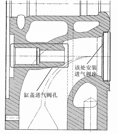
[0027] Below in conjunction with accompanying drawing and embodiment, the present invention is used for PC26 type cylinder head intake valve seat installation to be described in further detail, but can not limit the scope of protection of the present invention with this.

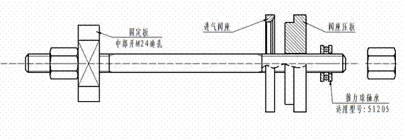
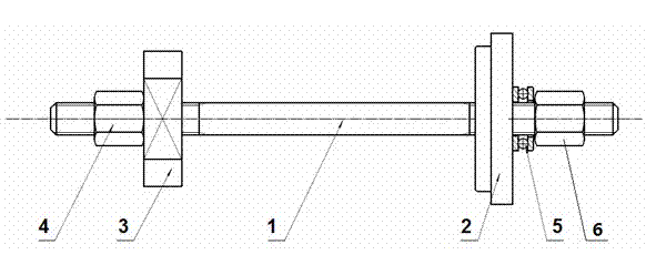
[0028] Please see first figure 2 , figure 2 It is a structural schematic diagram of the device for valve seat installation of the present invention. As shown in the figure, a device for valve seat installation includes a pull rod 1 with threads at both ends, a fixing plate 3 and a pressure plate 2 are respectively arranged at both ends of the pull rod 1, and the fixing plate 3 and the pressure plate 2 A first compression nut 4 and a second compression nut 6 are respectively installed on the outside of the outer side to fix the fixing plate 3 and the pressure plate 2 on both ends of the tie rod 1 . An axial ball bearing 5 is installed between the pressing plate 2 and the compression nut 4 outside the pres...


PUM


Abstract

The invention discloses a device for mounting a valve seat. The device comprises a pull rod, of which two ends are provided with screw threads, wherein the two ends of the pull rod are provided with a fixing plate and a pressing plate respectively; and a first gland nut and two second gland nuts are arranged on the outer side of each of the fixing plate and the pressing plate, and are used for fixing each of the fixing plate and the pressing plate at each of the two ends of the pull rod. During mounting, the pull rod passes through an air inlet valve hole in a cylinder cover; the nuts and the fixing plate are arranged on the side opposite to the valve seat to fix the pull rod; and the gland nuts and the pressing plate are arranged on the valve seat side to mount the valve seat in a valve seat hole in the cylinder cover in a squeezed manner. The mounting process for the valve seat is simplified greatly, and the mounting time is reduced, so that the valve seat mounting operation is relatively safe; and the device is particularly suitable for mounting the valve seats of air inlet valves of PC26-type cylinder covers.

Description

technical field [0001] The invention relates to the technical field of valve seat installation, in particular to a device for installing a PC26 cylinder head valve seat and a method for installing the valve seat. Background technique [0002] During the installation of the cylinder head valve seat, a steady and continuous pressure is required to squeeze the valve seat into the valve seat hole of the cylinder head; according to the design size of the valve seat and the valve seat hole, there is a gap of 0.175-0.22mm between the valve seat and the seat hole. According to the calculation, a pressure of about 3.4 tons is required to install the valve seat in place, and finally it should be completely attached to the cylinder head; during the installation of the valve seat, it should be ensured that the valve seat is kept horizontal relative to the cylinder head, otherwise it may be in the During the installation process, it is stuck due to the inclination of the valve seat. [...

Claims


Application Information

Patent Timeline
Patent Type & Authority Applications(China)
IPC IPC(8): B25B27/02
Inventor 周柯
Owner HUDONG HEAVY MACHINERY
Why Eureka
Try Eureka