Elastic buffering hydraulic cylinder

A hydraulic cylinder and elastic cushioning technology, which is applied in the field of hydraulic cylinders, can solve problems such as insufficient cushioning capacity, reduced service life, and poor safety effects, and achieve the effects of stable energy output, simple structure, and convenient installation

Inactive Publication Date: 2012-06-27
山东天一液压科技股份有限公司
View PDF4 Cites 5 Cited by
  • Summary
  • Abstract
  • Description
  • Claims
  • Application Information

AI Technical Summary

Problems solved by technology

[0002] In the single-piston hydraulic cylinder in the prior art, one end of the piston enters oil and the other end outputs oil. When conventional hydraulic cylinders are used in heavy hydraulic machinery such as weight lifters, excavators, bulldozers, forklifts, etc., there is often hydraulic oil leakage. Poor safety effect and insufficient buffer capacity
[0003] At the same time, because the traditional hydraulic cylinders are basically exposed during operation, most of them do not have protective covers, so the hydraulic cylinders, especially the piston rod structure, are not well protected, and dust and foreign objects in the environment are easy to collide or enter the hydraulic cylinders , so as to wear and damage the cylinder, making the leakage more serious, reducing the service life and greatly increasing the failure rate

Method used


Image

  • Elastic buffering hydraulic cylinder
  • Elastic buffering hydraulic cylinder
  • Elastic buffering hydraulic cylinder

Examples


Embodiment Construction

[0015] The present invention will be described in detail below in conjunction with the accompanying drawings.

[0016] Figure 1-3 Described is the first embodiment of the present invention.

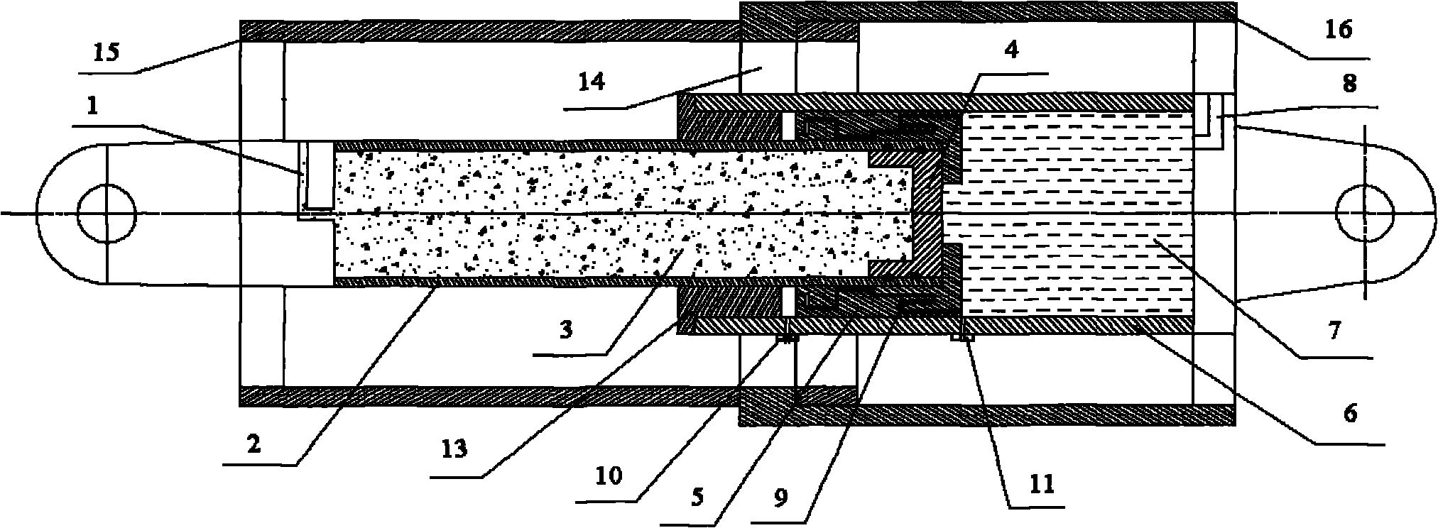
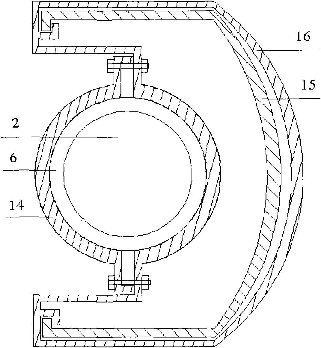
[0017] first reference Figure 1 to Figure 2 , figure 1 It is a structural schematic diagram of the hydraulic cylinder of the present invention. A piston rod 2 is installed in the cylinder body 6, and an oil chamber 7 is arranged inside the cylinder body 6. The piston rod is a hollow structure, and an air chamber 3 is arranged inside, and a piston 4 is arranged in the air chamber 3, and the piston 4 connects the air chamber 3 and the oil chamber. The cavity 7 is separated, the air cavity 3 is provided with an air inlet 1 for compressed gas, the oil chamber 7 is provided with an oil inlet 8 for hydraulic oil, and the cylinder body is provided with a pressure sensor 11 to detect the internal pressure of the oil cylinder. The oil and gas separation is realized by the piston between the ...


PUM


Abstract

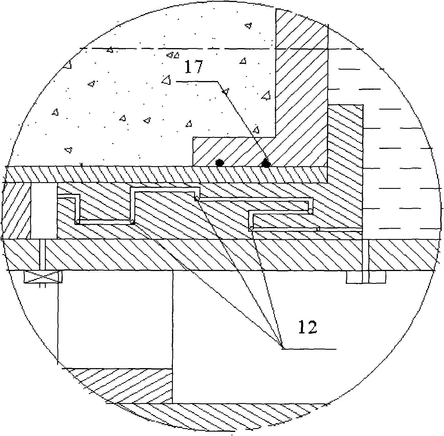
The invention discloses an elastic buffering hydraulic cylinder, which comprises a piston rod, a cylinder body and a piston, wherein the piston rod has a hollow structure, and a gas cavity is formed in the piston rod; an oil cavity is formed in the cylinder body; high-pressure nitrogen is filled in the gas cavity, and hydraulic oil is filled in the oil cavity; the piston is arranged in the piston rod, and the gas cavity and the oil cavity are partitioned through the piston; an O-shaped sealing ring is arranged between the piston and the inner wall of the piston rod, and a connecting device is also arranged between the piston rod and the cylinder body; a fixed cover is arranged on the outer part of the cylinder body, and a cavity is formed in the fixed cover; a movable cover is arranged on the outer part of the piston rod, the movable cover is a metallic corrugated pipe device, a groove is formed in the cavity of the fixed cover, and the movable cover is embedded into the fixed cover through the groove; and a labyrinth passage is formed between the connecting device and the inner wall of the cylinder body, and a plurality of steel balls for separating the hydraulic oil from the gas are arranged in the labyrinth passage. The protective cover is arranged outside the elastic buffering hydraulic cylinder, and an internal medium is safe and leak-free, so that effective elastic buffering is produced in a compression travel.

Description

technical field [0001] The invention relates to an elastic cushioning hydraulic oil cylinder, in particular to a hydraulic oil cylinder which uses high-pressure nitrogen to play a buffering role and has a protective device. Background technique [0002] In the single-piston hydraulic cylinder in the prior art, one end of the piston enters oil and the other end outputs oil. When conventional hydraulic cylinders are used in heavy hydraulic machinery such as weight lifters, excavators, bulldozers, forklifts, etc., there is often hydraulic oil leakage. The safety effect is poor and the buffer capacity is not enough. [0003] At the same time, because the traditional hydraulic cylinders are basically exposed during operation, most of them do not have protective covers, so the hydraulic cylinders, especially the piston rod structure, are not well protected, and dust and foreign objects in the environment are easy to collide or enter the hydraulic cylinders , thus wearing and dest...

Claims


Application Information

Patent Timeline
Patent Type & Authority Applications(China)
IPC IPC(8): F15B15/14F15B15/22F15B15/20
Inventor 楼天汝
Owner 山东天一液压科技股份有限公司
Why Eureka
Try Eureka