Power transmission module with self-locking mechanism

A technology of power transmission and self-locking mechanism, applied in mechanical equipment, transmission devices, gear transmission devices, etc., can solve the problems of energy waste and safety, heavy objects falling, loss of power source of power transmission modules, etc., to achieve optimal control and stability performance, reducing the risk of burnout, saving energy consumption

Inactive Publication Date: 2012-06-27
戴文钟
View PDF7 Cites 5 Cited by
  • Summary
  • Abstract
  • Description
  • Claims
  • Application Information

AI Technical Summary

Problems solved by technology

Although this method can prevent the servo motor from being burnt due to overload, since the servo motor will not generate driving force through electromagnetic effects after power failure, not only the entire power transmission module will lose its power source, but the rotor of the servo motor will also be damaged. Pushed by an external force and free to rotate, the various components in the power transmission module that were originally driven by the servo motor lose their binding force instantly, and cannot maintain their predetermined positions or angles. What's more, if the power transmission module is under load When the heavy object is in the state, if the servo motor no longer outputs the driving force, the heavy object will fall due to the loss of support, and the consequences are even more dangerous
[0005] To sum up, it can be seen that, due to the power mechanism used in the known mechanical device, its power source and the reaction force required to resist the external force are all derived from the driving force generated by the electric motor through the electromagnetic effect, which can easily cause energy loss. Concerns about waste and safety, therefore, how to improve the many problems existing in the known power transmission module, so as to improve the stability of power output and control, and at the same time achieve the effect of energy saving, and prevent the actuator from being damaged due to high torque. Burning is an important problem that needs to be solved urgently

Method used


Image

  • Power transmission module with self-locking mechanism
  • Power transmission module with self-locking mechanism
  • Power transmission module with self-locking mechanism

Examples


Embodiment Construction

[0045] The present invention will be further described below in conjunction with the accompanying drawings and embodiments.

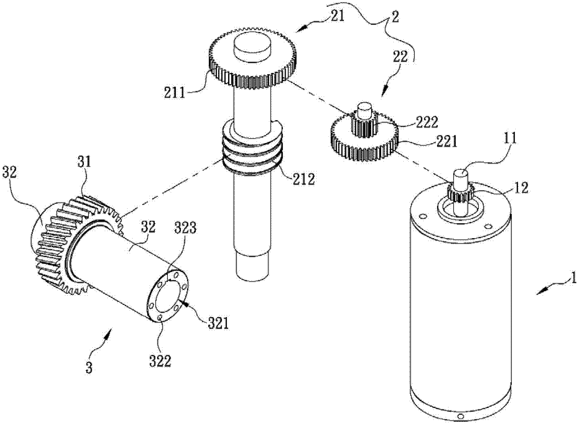
[0046] Such as figure 1As shown, the power transmission module with self-locking mechanism of the present invention includes an actuator 1, a reduction mechanism 2 and a driven shaft 3, wherein the actuator 1 can be a DC motor, an AC induction motor, an AC synchronous motor, a switch type Reluctance motors or stepping motors, etc., during production, manufacturers can choose motors with different characteristics according to their needs, or design servo motors with other feedback devices (such as: photoelectric encoders or resolvers, etc.). A driving shaft 11 of the actuator 1 is provided with a coaxially rotating driving gear 12, and the driving shaft 11 can rotate together with the driving gear 12; in this embodiment, the reduction mechanism 2 includes a transmission shaft 21 and a Reduction gear 22, drive shaft 21 is provided with a driven gear 211 ...


PUM


Abstract

The invention discloses a power transmission module with a self-locking mechanism. The power transmission module comprises an actuator, a reducing mechanism and a driven shaft, wherein the actuator is provided with a driving shaft; a driving gear which coaxially rotates is arranged on the driving shaft; the reducing mechanism comprises a transmission shaft provided with a driven gear and a driving worm respectively; the driven gear is directly meshed with the driving gear or meshed with the driving gear through a reducing gear; the driven shaft is provided with a driven worm meshed with the driving worm; and the meshed part of the driven worm and the driving worm is provided with a worm gear lead angle capable of generating a self-locking effect, so that the driving worm cannot be driven by the driven worm. Compared with the prior art, the power transmission module has a self-locking function, is energy-saving, stable and high in safety, has excellent control stability, and can greatly reduce a danger that the actuator bears high torque and is burnt down.

Description

technical field [0001] The invention relates to a power transmission module with a self-locking mechanism. Background technique [0002] With the development of industry, all kinds of mechanical devices have been widely used in various fields. Under the mutual cooperation of actuators and various transmission mechanisms, various mechanical devices are based on their different functional orientations. Not only can it perform simple and repetitive actions, or carry work that cannot be afforded by manpower, but it can also accurately execute people’s pre-set action instructions. Even the precision instruments used by research institutes have brought a lot of convenience to people's life and work through the collocation of various ingenious mechanisms, and have also greatly changed the patterns of people's life and work. In various mechanical devices, the actuator is almost an essential component, because the actuator can convert other forms of energy (such as: electricity) int...

Claims


Application Information

Patent Timeline
Patent Type & Authority Applications(China)
IPC IPC(8): F16H1/20
Inventor 戴文钟
Owner 戴文钟
Why Eureka
Try Eureka