Bisection moving rocker arm mechanism driven by worm wheel and worm

A technology of worm gear and rocker mechanism, which is applied in gear transmission, mechanical equipment, transmission, etc., can solve the problems of inability to meet functional requirements, inability to achieve self-locking function, and insufficiently compact structure, and achieve low noise and simple structure. , the effect of enhancing the carrying capacity

Inactive Publication Date: 2012-06-27
BEIHANG UNIV
View PDF7 Cites 6 Cited by
  • Summary
  • Abstract
  • Description
  • Claims
  • Application Information

AI Technical Summary

Problems solved by technology

Most of the existing rocker arm mechanisms use an oil cylinder structure to drive the rocker arm to rotate, or a pull rod mechanism to drive. These structures occupy a large space, are not compact enough, and cannot realize the self-locking function. Poor safety performance
Moreover, in the existing rocker arm structures, most of them realize the movement of a single rocker arm. In some cases where two rocker arms or even multiple rocker arms are required to move together, the functional requirements cannot be met.

Method used


Image

  • Bisection moving rocker arm mechanism driven by worm wheel and worm
  • Bisection moving rocker arm mechanism driven by worm wheel and worm
  • Bisection moving rocker arm mechanism driven by worm wheel and worm

Examples


Embodiment Construction

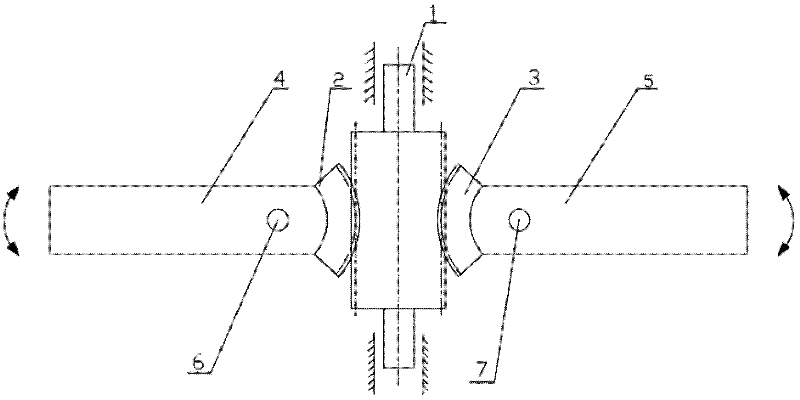
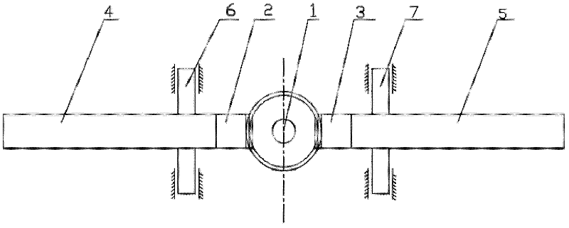
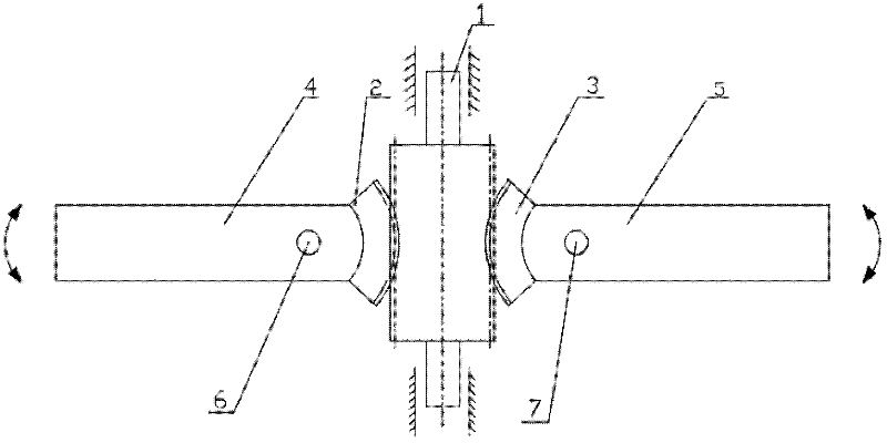
[0031] See figure 1 , figure 2 , the present invention is a worm gear driven bisecting motion rocker mechanism, which is composed of a worm 1, a left worm wheel 2, a right worm wheel 3, a left rocker arm 4, a right rocker arm 5, a left shaft 6 and a right shaft 7, among them The position connection relationship among them is: the worm 1 meshes with the left worm gear 2 and the right worm gear 3 respectively; the left worm gear 2 and the right worm gear 3 are rigidly connected with the left rocker arm 4 and the right rocker arm 5 respectively; The centerlines of the left and right turbines coincide with the centerlines of the left turbine 2 and the right turbine 3 respectively; the left shaft 6 and the right shaft 7 are fixedly connected to the left rocker arm 4 and the right rocker arm 5 respectively;

[0032] The worm 1 is made of a cylindrical stepped shaft with an axial modulus of 3.15, an axial head number of 1, and a lead angle of 15°;

[0033] The left turbine 2 is a ...


PUM


Abstract

The invention discloses a bisection moving rocker arm mechanism driven by worm wheels and a worm, which comprises a worm, a left worm wheel, a right worm wheel, a left rocker arm, a right rocker arm, a left shaft and a right shaft, wherein the worm is respectively meshed with the left worm wheel and the right worm wheel; the left worm wheel and the right worm wheel are respectively rigidly connected with the left rocker arm and the right rocker arm; the center line of the left shaft and the center line of the right shaft are respectively coincident with the center line of the left worm wheel and the center line of the right worm wheel; the left shaft and the right shaft are respectively fixedly connected with the left rocker arm and the right rocker arm; the left worm wheel and the right worm wheel are driven by the worm to rotate relatively to the respective center line, i.e. the left shaft and the right shaft; and the left rocker arm and the right rocker arm fixedly connected with the left worm wheel and the right worm wheel are driven to respectively move relatively to the left shaft and the right shaft so as to realize the moving bisection of the two rocker arms. The bisection moving rocker arm mechanism driven by the worm wheels and the worm has the advantages of compact structure, excellent performance and good application prospect in the technical field of machinery and automotive engineering, and the bisection movement and the self-locking function of the mechanism can be realized.

Description

technical field [0001] The invention relates to a mechanical rocker mechanism, in particular to a turbine and worm driven bisecting motion rocker mechanism, which is a rocker mechanism capable of bisecting motion and belongs to the technical field of machinery and automobile engineering. Background technique [0002] The rocker arm mechanism is widely used in the field of mechanical and automotive engineering technology. Its main form is that a certain point in the middle of the rocker arm is hinged, which can realize the movement arm rotating around the hinge point. Now it is mainly used in the coal mining device of the coal mining machine, and the valve control in the engine device, as well as in the landing gear of the aircraft. Most of the existing rocker arm mechanisms use an oil cylinder structure to drive the rocker arm to rotate, or a pull rod mechanism to drive. These structures occupy a large space, are not compact enough, and cannot realize the self-locking functi...

Claims


Application Information

Patent Timeline
Patent Type & Authority Applications(China)
IPC IPC(8): F16H1/22F16H55/22F16C3/02
Inventor 高峰崔莹徐国艳徐丽丽王晓坡解晓琳白锦洋
Owner BEIHANG UNIV
Why Eureka
Try Eureka