Optical film set and backlight module employing same

A backlight module and optical film technology, applied in optics, nonlinear optics, electric light sources, etc., can solve the problems of adding a backlight module 100 manufacturing trouble, installation and manufacturing difficulty, etc., to simplify the manufacturing and assembly process, and improve the problem of light leakage. Effect

Inactive Publication Date: 2012-06-27
AU OPTRONICS CORP
View PDF5 Cites 17 Cited by
  • Summary
  • Abstract
  • Description
  • Claims
  • Application Information

AI Technical Summary

Problems solved by technology

In addition to the problem of the above-mentioned installation sequence, the size of this type of light-shielding assembly is usually small, so it is not easy to install and manufacture, which adds to the troubles in the manufacture of the backlight module 100

Method used


Image

  • Optical film set and backlight module employing same
  • Optical film set and backlight module employing same
  • Optical film set and backlight module employing same

Examples


Embodiment Construction

[0051] Below in conjunction with accompanying drawing, structural principle and working principle of the present invention are specifically described:

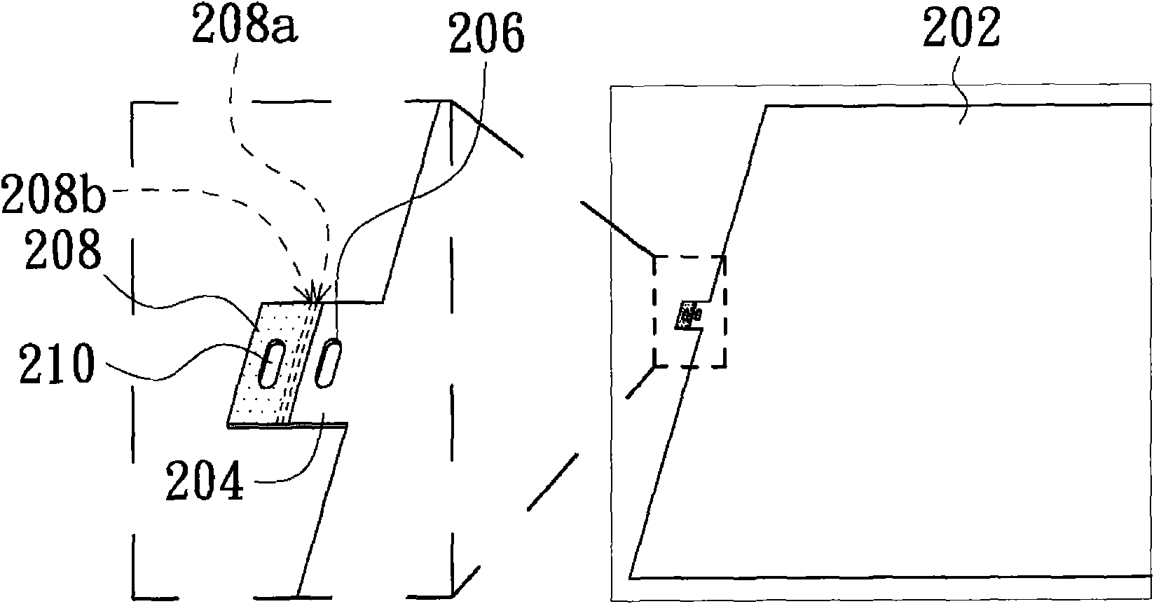
[0052] Please refer to Figure 2A , Figure 2A It is a partial appearance schematic diagram of the first embodiment of the present invention. Such as Figure 2A As shown, the optical film 202 of the first embodiment of the present invention has four sides (not shown in the figure), which are the upper side, the lower side, the left side and the right side. The four sides make the optical film 202 roughly in a rectangular shape. For the convenience of explanation, Figure 2A Only the upper side, lower side, and left side are shown in the middle.

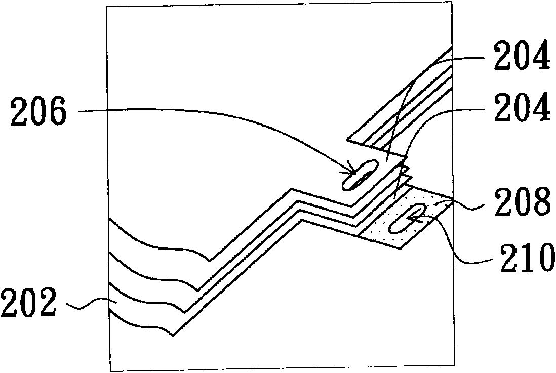
[0053] A protruding portion 204 extending outward and a light shielding portion 208 extending outward from the edge of the protruding portion 204 are formed at a specific position on the left side of the optical film 202 . The protruding portion 204 and the light shielding porti...


PUM


Abstract

Disclosed are an optical film set and a backlight module employing same. The optical film set comprises a first optical film with at least one first protrusion portion, a second optical film arranged at one side of the optical film and having a second protrusion portion correspondingly arranged on the upper or lower surfaces of the first protrusion portion, a light shielding portion which extends out from the second protrusion portion and is overturned to wrap up the side of the first protrusion portion of the first optical film. The backlight module comprises a frame with at least one groove, a plurality of optical films installed on the frame, each of which has a protrusion corresponding to the groove of the frame, and a light shielding portion integrally extending out from the protrusion portion of any one optical film to be overturned and wrap up sides of the protrusion portion of other optical films.

Description

technical field [0001] The invention relates to an optical film and a backlight module, in particular to an optical film group capable of avoiding light leakage and a backlight module using the optical film group. Background technique [0002] With the development of light-emitting technology, liquid crystal displays have been widely used in various information processing devices (eg, smart phones, tablet computers, notebook computers, navigation devices, etc.) in recent years. Most of the current liquid crystal displays are light and thin as the appeal of the product. Generally speaking, a common liquid crystal display adopts a structure of thin film transistors. Therefore, the liquid crystal display needs to be equipped with a light source of a backlight module to achieve the image display effect. [0003] Generally speaking, a backlight module can be composed of components such as a frame, an optical film, a light source, and a light guide plate. Due to the process (for...

Claims


Application Information

Patent Timeline
Patent Type & Authority Applications(China)
IPC IPC(8): F21V5/02F21S8/00G02F1/13357
Inventor 王呈钰萧予菱蔡政旻
Owner AU OPTRONICS CORP
Why Eureka
Try Eureka