
Power network topology dynamic coloring algorithm

A coloring algorithm and power network technology, applied in the field of power, can solve the problem of monitoring system losing the dynamic coloring function of network topology, and achieve the effect of strong scalability, simple principle and good versatility

Active Publication Date: 2012-06-27
GUODIAN NANJING AUTOMATION
View PDF2 Cites 12 Cited by
  • Summary
  • Abstract
  • Description
  • Claims
  • Application Information

AI Technical Summary

Problems solved by technology

When the network topology analysis module fails, the monitoring system will also lose the dynamic coloring function of the network topology

Method used


Image

  • Power network topology dynamic coloring algorithm
  • Power network topology dynamic coloring algorithm
  • Power network topology dynamic coloring algorithm

Examples


Embodiment 1

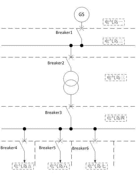
[0038] according to figure 1 For the power network shown, the specific definition of the electrical island is as follows:

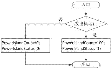
[0039] 1. The electrical island is the generator GS system, which is the source of power in the system. It is an active electrical island, which is defined as PowerIsland1, and PowerIslandCount1 is used to indicate the charged state. The value is a positive integer indicating that it is charged, and the value is 0. It indicates that it is not charged; PowerIslandStatus1 indicates whether to display electrification, a value of 0 indicates no display, and a value of 1 indicates display. use figure 2 The active electrical island algorithm is shown.

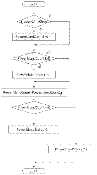
[0040]2. The electrical island 2 is a two-port passive electrical island, which is defined as PowerIsland2, and PowerIslandCount2 is used to indicate the charging status, and PowerIslandStatus2 indicates whether it is charged or not. use Figure 4 The passive electrical island algorithm is shown.

[0041] ...

Embodiment 2

[0071] In the steps in the first embodiment, it can be seen that the change of the charged state of the electrical island and the position of the switch will lead to some backtracking calculations. According to the operating characteristics of the power network, we know that the current flows from the power supply end to the power receiving end, and no power will be generated. "Backward" situation. Therefore, the ports of the electrical island can be defined as power supply port and power receiving port respectively. Hence in figure 1 The power network can be regarded as a directed graph, and the definition method is optimized as follows:

[0072] 1. The electrical island is the generator GS system, which is the power source in the system. It is an active electrical island, which is defined as PowerIsland1. PowerIslandCount1 indicates the charged status, and PowerIslandStatus1 indicates whether it is charged. use figure 2 The active electrical island algorithm is shown.

...


PUM


Abstract

The invention discloses a power network topology dynamic coloring algorithm which comprises the following steps of: defining active N-port elements and passive N-port elements into substation islands which are charged or not and substation islands which display a charged color or not; abstracting a power network into connection between the active N-port elements and the passive N-port elements, which is carried out by switching equipment; starting a computing service process and maintaining threads of which the number corresponds to the number of the substation islands; and when the variation of a power generating state of each substation island, a switching state associated with the substation island or a charged state of the adjacent substation island is detected, executing the thread for once to obtain the charged state of the substation island. The algorithm disclosed by the invention is irrelevant with a network topology structure; a network topology dynamic coloring function and a network topology analysis function are decoupled; different charged algorithms are selected for the properties of the substation islands; and times of backtracking and calculation are reduced. The network topology dynamic coloring of a power grid with a complex structure can be realized. The power network topology dynamic coloring algorithm has excellent practicality, strong expansibility and rapidity.

Description

technical field [0001] The invention relates to a power network topology dynamic coloring algorithm, which belongs to the technical field of electric power. Background technique [0002] Dynamic coloring of power system network topology refers to determining the charged state of the network and analyzing the power supply state of the power grid based on the real-time operating state of the equipment, which is an important function of the power management system. An important requirement for the dynamic coloring of the power network topology is the real-time, rapidity and accuracy of the dynamic coloring. When the power generation status of the generator, the position of the circuit breaker or the switch changes, the power supply status of the grid is immediately given, and the status of the grid is displayed. Network topology coloring changes immediately. [0003] Computer monitoring systems are generally divided into program modules according to their functions, and many f...

Claims


Application Information

Patent Timeline
IPC IPC(8): G06F19/00
Inventor 颜儒彬包德梅
Owner GUODIAN NANJING AUTOMATION
Learn More