Spring-ring type inserting hole and inserting needle thereof

A spring coil and pin technology, which is applied to contact parts, electrical components, coupling devices, etc., can solve the problems of long plug-in sections of high-current connectors, difficult to meet high-current conditions, and large size, and achieves a solution to plug-in The effect of segment length, high practical value and large contact area

Inactive Publication Date: 2012-06-27
ZHEJIANG ZHONGHANG ELECTRONICS
View PDF5 Cites 31 Cited by
  • Summary
  • Abstract
  • Description
  • Claims
  • Application Information

AI Technical Summary

Problems solved by technology

[0003] The purpose of the present invention is to solve the problem that the contact area between the pin and the socket in the prior art is small, and it is difficult to meet the high-current working condition, and to provide a connector with a large contact area between the pin and the socket, which can meet the high-current working condition. Spring coil jack and its pins
[0004] Another object of the present invention is to solve the problems of the prior art high-current connectors with long insertion section, large volume, and complex structure, and provide a short insertion section between the pin and the socket, small volume, simple structure, and low production cost. Low spring coil jack and its pins

Method used


Image

  • Spring-ring type inserting hole and inserting needle thereof
  • Spring-ring type inserting hole and inserting needle thereof
  • Spring-ring type inserting hole and inserting needle thereof

Examples


Embodiment 1

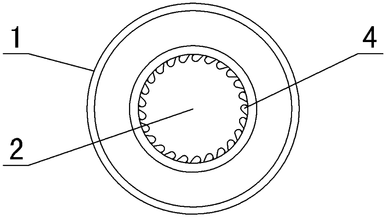
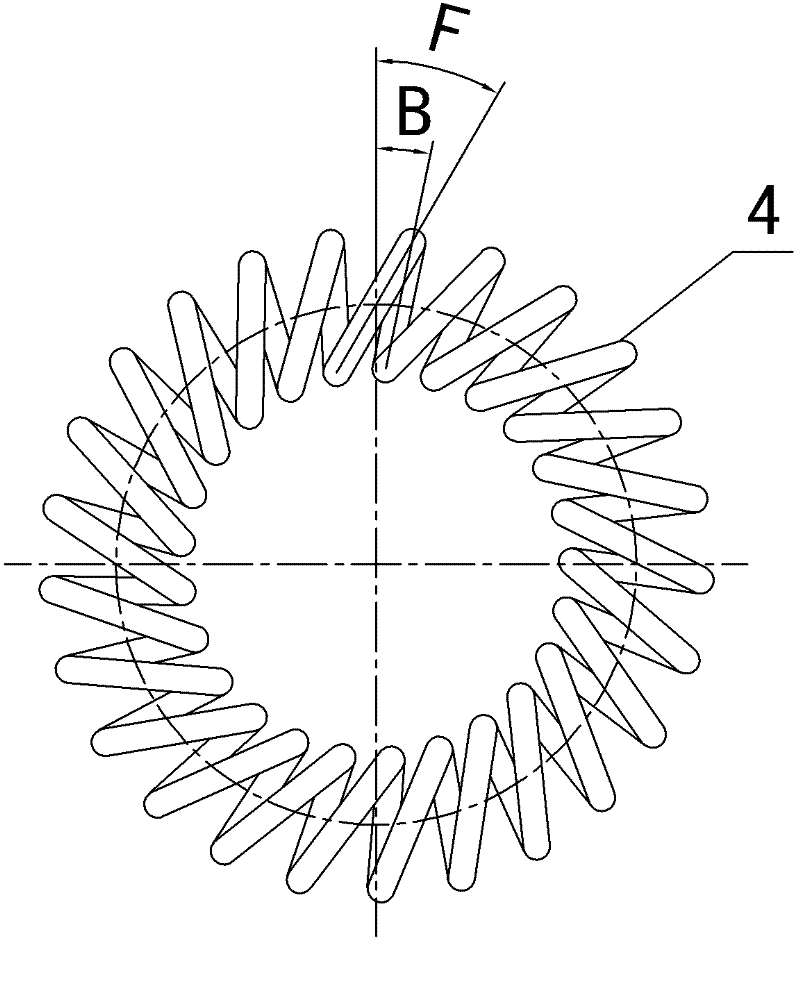
[0029] in such as figure 1In the shown embodiment, a spring coil socket includes a socket body 1 provided with a circular pin hole 2 and a wiring hole 11, and a U-shaped cross section is provided on the inner wall of the pin hole. Shaped annular groove 3, the circular groove is provided with a helical coil 4 with a circular cross section, the inner diameter of the helical coil is smaller than the aperture of the pin hole (see figure 2 ), the depth of the annular groove is 60% of the radial outer diameter of the helical spring constituting the helical spring coil. The height of the spring ring is consistent with the width of the annular groove. The helical spring 5 that constitutes the helical spring ring is an oblique spring, and the helix angle of the helical spring ring changes periodically. The forward inclination angle F between the shaft sections is 30 degrees, and the back inclination angle B between the projection line of the spring line on the other side on the horiz...

Embodiment 2

[0032] in such as Figure 5 In the shown embodiment 2, the cross-section of the helical spring coil is elliptical, and the major axis of the ellipse is parallel to the axis of the pin hole. The spring ring is suitable, and the depth of the annular groove is 70% of the outer diameter of the helical spring constituting the helical spring ring in the radial direction of the helical spring ring, and all the other are the same as in embodiment 1.

Embodiment 3

[0034] in such as Image 6 In the shown embodiment 3, two annular grooves are provided on the inner wall of the pin insertion hole, and a helical spring coil with a circular cross section is provided in the annular groove, and the helical spring coils in the two annular grooves have opposite directions of rotation.

[0035] The pins that are compatible with the spring coil jack of this embodiment are as follows: Figure 10 As shown, the pin head is provided with two arc-shaped grooves surrounding the outer peripheral surface of the pin head. The position of the arc-shaped grooves matches the annular groove in the pin hole of Embodiment 3, and the rest is the same as Embodiment 1.


PUM


Abstract

The invention discloses a spring-ring type inserting hole and an inserting needle thereof, wherein a ring-shaped slot with a U-shaped cross section is arranged on the inner wall of an inserting-needle hole, a spiral spring ring is arranged in the ring-shaped slot, the inside diameter of the spiral spring ring is smaller than the aperture of the inserting-needle hole, the height of the spiral spring ring is consistent with the width of the ring-shaped slot, and a spiral spring forming the spiral spring ring is an oblique spring; and arc-shaped slots surrounding the outer circumferential surface of an inserting-needle head are arranged on the inserting-needle head which is adapted to the inserting hole, and the quantity and the positions of the arc-shaped slots are adapted to the ring-shaped slot in the inserting-needle hole. Through the spring-ring type inserting hole and the inserting needle of the spring-ring type inserting hole, the problem that a connector in the prior art difficultly meets the requirement of a large-current working condition is effectively solved, and the spring-ring type inserting hole and the inserting needle of the spring-ring type inserting hole disclosed by the invention have large contact areas, small sizes and simple structures, are connector parts with bran-new structures and have high practical value.

Description

technical field [0001] 本发明涉及电连接器技术领域,尤其涉及一种用于大电流接插件的弹簧圈式插孔及其插针。 Background technique [0002] 在电连接器中,接插件的插针与插孔的接触面积是衡量接插件的重要技术指标,尤其是工作在大电流工况下的接插件。在现有技术中,一般片簧的接触面积在30%左右,目前最好的冠簧、线簧孔结构的电连接器其接触面积也只有50%至60%,因此这类结构很难在大电流的接插件上使用,比如对于单芯工作电流在3000安培以上的接插件,现有技术的插针插孔结构就很难实现。公开日为2010年7月21日,公开号为CN101782456A的中国专利文件公开了一种用于高温环境的电连接器,涉及一种用于与互相配合的连接器建立电接触的电连接器,特别用于高温环境下,该电连接器包括:外壳,具有基本上为圆柱形的内部空间且至少一端开口;细长的接触单元,设置在内部空间中.当互相配合的连接器引入该内部空间时,该接触单元与互相配合的连接器接触;以及细长的弹性单元,设置在内部空间的侧壁与接触单元之间,以弹性支撑该细长的接触单元,其中该接触单元包括夹在壳体的第一和第二部分之间的固定部。公开日为2011年2月9日,公开号为CN101969160A的中国专利文件公开了一种冠簧笼式插孔及其冠簧,该插孔包括内套,内套的内孔中穿设冠簧,冠簧包括位于两端的同轴设置的两端环,两端环之间一体连接设置有连接线簧条,各连接线簧条的延伸方向与两端环的轴线空间相交并相对于端环的轴线同趋势偏斜。由于冠簧的两端设有端环,端簧将原本离散的线簧条连接为一个整体,使冠簧的整体性变强,不易损坏。上述两种专利都是对现有接插件线簧结构的改进,主要是为了解决线簧容易断裂的问题,插针与插孔的接触面积也有一定的增加,但上述专利结构复杂,插接段较长,要使接插件可以在大电流下工作,接插件的体积就会变得很大,大大增加了成本和局限了适用范围。 Contents of the invention [0003] 本发明的目的在于解决现有技术的接插件其插针与插孔接触面积小,难以满足大电流工况的问题,提供一种插针与插孔接触面积大,可以满足大电流工况的弹簧圈式插孔及其插针。 [0004] 本发明的另一目的在于解决现有技术的大电流接插件插接段长、体积大、结构复杂的问题,提供一种...

Claims


Application Information

Patent Timeline
Patent Type & Authority Applications(China)
IPC IPC(8): H01R13/04H01R13/187
Inventor 王吉国
Owner ZHEJIANG ZHONGHANG ELECTRONICS
Why Eureka
Try Eureka