
Power distribution cabinet system

A technology for power distribution cabinets and electrical systems, applied in the field of power distribution cabinet systems, can solve problems such as hidden safety hazards, decreased insulation performance, insufficient electrical clearance, etc., and achieve the effect of removing hidden dangers of composite insulation, reasonable and perfect layout, and beautiful appearance.

Inactive Publication Date: 2012-06-27
CNC ELECTRIC GRP
View PDF4 Cites 1 Cited by
  • Summary
  • Abstract
  • Description
  • Claims
  • Application Information

AI Technical Summary

Problems solved by technology

[0003] However, after the PT vehicle has added lightning arresters, voltage transformers, and fuses, the electrical clearance between the lightning arrester and the ground (PT vehicle support plate) is not enough, and the electrical clearance between the voltage transformer and the cabinet sealing plate is not enough. The usual solution is Add composite insulation, use heat shrinkable sleeve and insulation board, etc.
Although this can pass the power frequency withstand voltage test, the appearance is extremely ugly, and there are also potential safety hazards. The insulating material is affected by temperature rise, electric field, dust pollution, moisture, etc., and its insulation performance will continue to decline over time. Once insulation breakdown occurs, the consequences will be serious
Moreover, the electrical clearance between the terminal of the arrester and the voltage transformer does not meet the standard requirements. Although their potentials are equal during normal operation, when the fuse is blown, there will be a potential difference between the two, and there will be a discharge phenomenon. Serious threat to the security of the device

Method used


Image

  • Power distribution cabinet system
  • Power distribution cabinet system
  • Power distribution cabinet system

Examples


Embodiment Construction

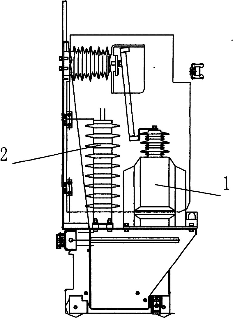
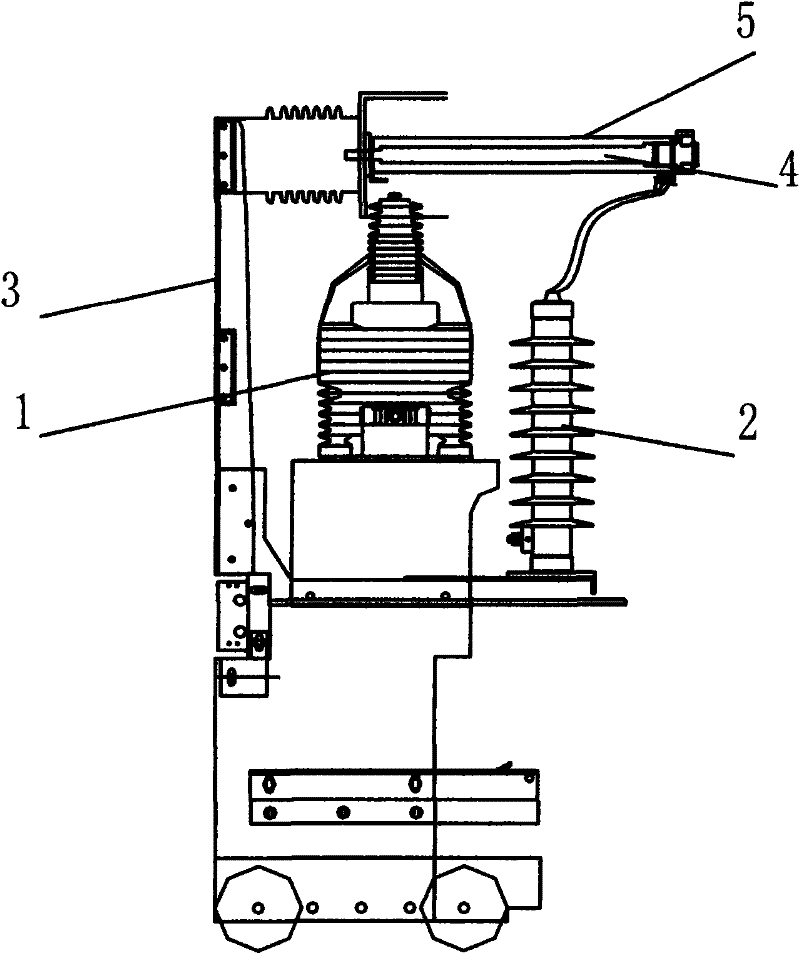
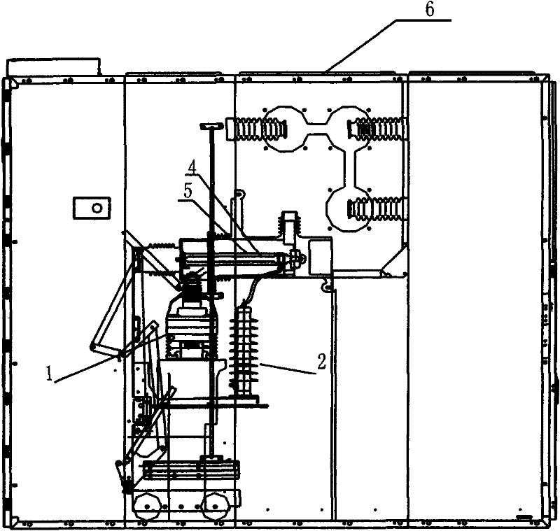
[0012] A power distribution cabinet system, comprising a cabinet body 6, the cabinet body 6 is provided with a primary electrical system, a switch cabinet, a contact box and a support plate 3 on the side of the PT vehicle, and the upper end of the support plate 3 is connected to the The contact arm 5 is connected, and a fuse 4 is arranged in the contact arm 5; the PT car is divided into upper and lower layers, the upper surface of which is connected with the voltage transformer 1, and the lower surface is connected with the lightning arrester 2; the lightning arrester 2 The upper end is connected with the external lead of the copper bar arranged at the port of the fuse 4 through a conductive connector; the contact arm 5 is made of insulating material.

[0013] The present invention considers the overall space, the circuit breaker room and the cable room sealing plate arranged in the cabinet body 6 are moved backward, and the primary bushing is moved up to expand the space of th...


PUM


Abstract

The invention discloses a power distribution cabinet system, which comprises a cabinet (6). A primary electrical system, a switch cabinet, a contact box and a PT trolley are disposed in the cabinet (6). A supporting plate (3) is arranged on the lateral side of the PT trolley, the upper end of the supporting plate (3) is connected with a contact arm (5), and a fuse (4) is arranged in the contact arm (5). The PT trolley includes an upper layer and a lower layer, the surface of the upper layer is connected with a potential transformer (1), and the surface of the lower layer is connected with an arrester (2). The upper end of the arrester (2) is connected with a copper bar external lead arranged at a port of the fuse (4) through a conductive connector. The power distribution cabinet system has the advantages that the system is reasonable in layout, the structure of the system is greatly optimized with the internal fuse, and due to the design of mounting the arrester and the transformer in a layered manner and the design of a front arrester mounting plate, air clearance between electrical devices can be guaranteed, and potential risks of compound insulation can be relieved.

Description

technical field [0001] The invention relates to a power distribution cabinet system. Background technique [0002] The solution for the existing 40.5kV system high-voltage transformer cabinet is to install the fuse trolley, voltage transformer, lightning arrester and cable room for fixed installation. In the actual maintenance of voltage transformers and surge arresters, it often happens that they mistakenly enter the charged interval, causing personal injury and death accidents. In view of more and more accidents, the State Grid Corporation issued a document requiring that all arresters and voltage transformers of the 12kV and 40.5kV power grid systems be installed on PT (fuse-arrester-voltage transformer) vehicles. In this way, the PT car needs to be pulled out for maintenance. After pulling out, it is naturally completely isolated from the primary circuit, which avoids the occurrence of accidents. [0003] However, after the PT vehicle has added lightning arresters, vol...

Claims


Application Information

Patent Timeline
Patent Type & Authority Applications(China)
IPC IPC(8): H02B11/167H02B11/26
Inventor 胡中天张昌满
Owner CNC ELECTRIC GRP
Learn More