
Voltage balance and power balance control method of cascaded H bridge converter

A technology of voltage balance and balanced control, which is applied in the direction of converting AC power input to DC power output, output power conversion devices, electrical components, etc. Power and other issues, to achieve the effect of simple and convenient, large linear modulation area, avoiding capacitor damage

Active Publication Date: 2012-06-27
SOUTHEAST UNIV
View PDF6 Cites 16 Cited by
  • Summary
  • Abstract
  • Description
  • Claims
  • Application Information

AI Technical Summary

Problems solved by technology

Therefore, if the parameters of each H-bridge are different, or the loads on the DC side are unbalanced, the traditional control method cannot achieve the purpose of DC voltage balance.
[0004] Chinese patent CN1514525 carries out active power exchange between the cascaded H-bridges through an additional device, thereby realizing the balance control of the capacitor voltage, but this method needs to add additional devices, which increases the cost; Chinese patent CN1933274 and US invention patent US6075350 both A capacitive voltage balancing method without adding additional devices is proposed, but their essence is based on the change and difference of the active power flowing through each H bridge to obtain the variation of the modulation wave of each H bridge, which is superimposed on the initial modulation wave to form each H bridge. The actual modulation wave of the bridge; Chinese patent CN101599708 is a power balance method for cascaded multilevel inverters, but the power balance it refers to is only the distribution of active power on demand, and in fact it is only a voltage balance problem; in this case Under this condition, only the modulation ratio (amplitude of the modulating wave vector) of the modulating wave vector of each H-bridge changes, but the phase remains the same
They all take the voltage balance as the control target, and only realize the balance of the DC side voltage, that is, the distribution of active power on demand. However, this directly changes the reactive power of each H-bridge, making the reactive power shared by each H-bridge different. , resulting in a large difference in the voltage ripple of each DC side, which seriously affects the service life of the DC side capacitor

Method used

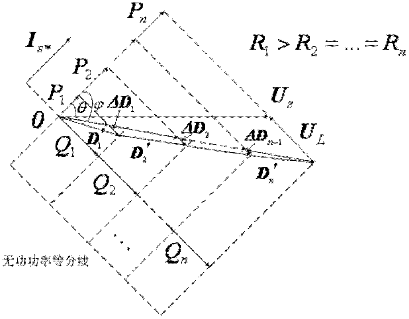
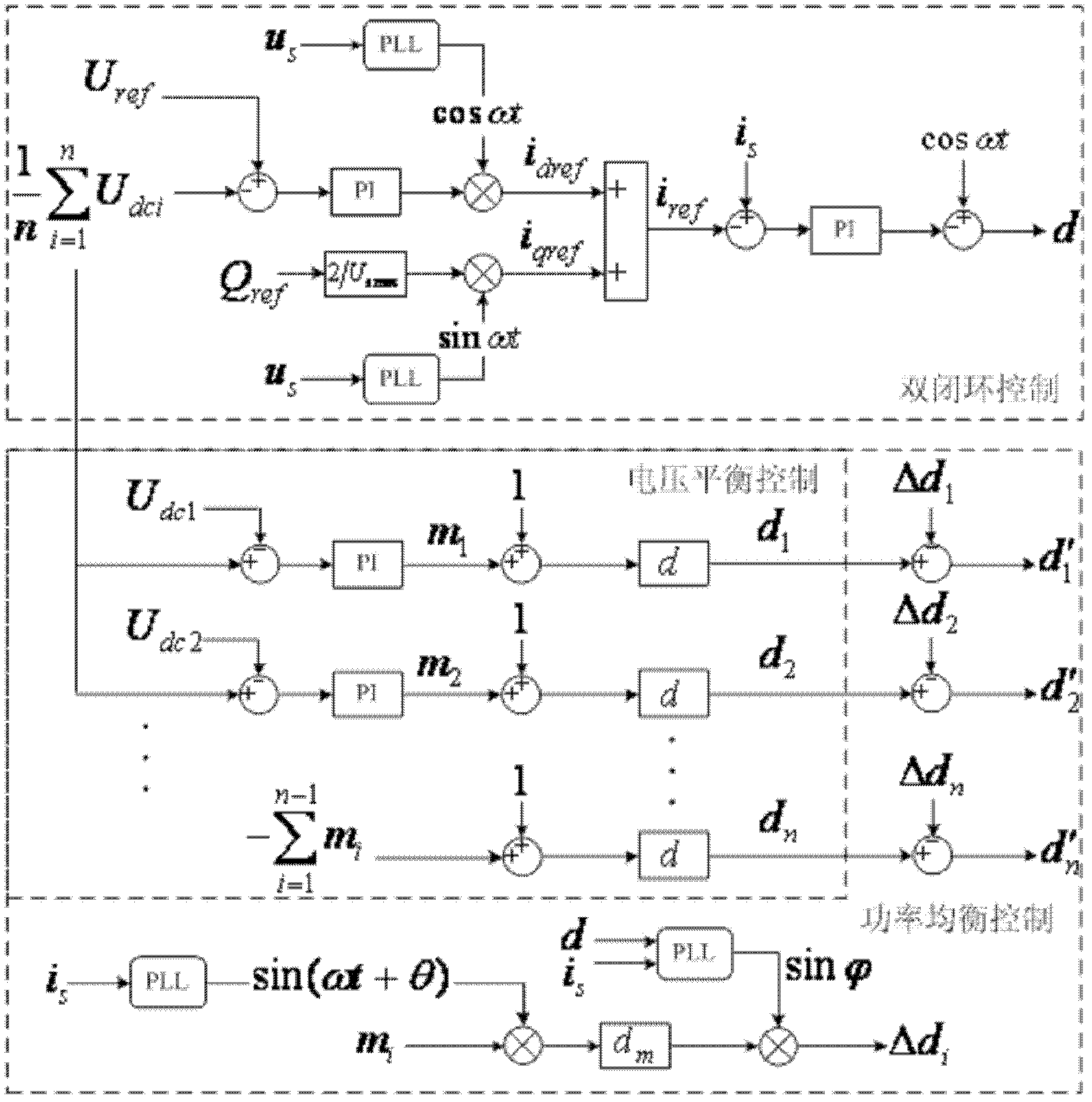

Image

  • Voltage balance and power balance control method of cascaded H bridge converter
  • Voltage balance and power balance control method of cascaded H bridge converter
  • Voltage balance and power balance control method of cascaded H bridge converter

Examples


Embodiment Construction

[0024] Below in conjunction with accompanying drawing and specific embodiment, further illustrate the present invention, should be understood that these embodiments are only for illustrating the present invention and are not intended to limit the scope of the present invention, after having read the present invention, those skilled in the art will understand various aspects of the present invention Modifications in equivalent forms all fall within the scope defined by the appended claims of this application.

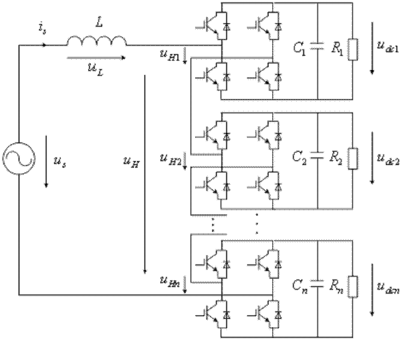
[0025] The present invention is mainly used for grid-connected control of cascaded H-bridge converters, and is widely used in static var compensators, power electronic transformers, and other occasions. The present invention will now be described by taking the working condition of power electronic transformers as an example. figure 1 Shown is a cascaded H-bridge topology, with R n To equivalent cascade H-bridge DC side load, R = ∞ is the static synchronous compensator wo...


PUM


Abstract

The invention discloses a voltage balance and power balance control method of a cascaded H bridge converter. The method comprises the following steps: (1) double closed loop control used for providing a same modulated wave vector to each H bridge; (2) voltage balance control; and (3) power balance control, wherein the voltage balance control and the power balance control improve a modulated wave vector respectively, and a reconstructed modulated wave vector is obtained and is taken as a modulation signal of each H bridge. According to the invention, adding an extra circuit is not needed, compared with a method of directly modifying a modulation ratio, direct current side voltage of each H bridge maintains balanced, voltage ripple is basically consistent, each H bridge flows through active power distributed according to needs, reactive power is distributed according to equivalent, and the method has a wider constraint scope and is suitable for an occasion of large load unbalance.

Description

technical field [0001] The invention belongs to the technical field of application of high-voltage and high-power power electronic technology in power systems, and in particular relates to a DC side voltage balance and power balance control method of a cascaded H-bridge converter. Background technique [0002] The cascaded H-bridge converter belongs to the multi-level technology. Compared with the clamp diode or clamp capacitive topology, it has a high degree of modularization and strong scalability, and is more suitable for high-voltage and high-power applications. It has been widely used in many high-voltage and high-power occasions such as inverters, static synchronous compensators, power electronic transformers, and photovoltaic grid-connected inverters. [0003] Cascaded H-bridge converters can be divided into two types: grid-connected and off-grid. The high-voltage inverter belongs to the application range of off-grid. Its DC side voltage relies on N independent DC sou...

Claims


Application Information

Patent Timeline
IPC IPC(8): H02M7/217
Inventor 赵剑锋孙毅超季振东于鹏
Owner SOUTHEAST UNIV
Learn More