Method for calibrating a multileaf collimator

A blade, detector technology used in the use of apertures/collimators, radiation therapy, character and pattern recognition, etc.

Inactive Publication Date: 2012-07-04
SIEMENS AG
View PDF4 Cites 16 Cited by
  • Summary
  • Abstract
  • Description
  • Claims
  • Application Information

AI Technical Summary

Problems solved by technology

[0009] The technical problem to be solved by the present invention is to design a less complex calibration method for the entire multi-leaf collimator system, wherein the multi-leaf collimator includes blades and blade holders

Method used


Image

  • Method for calibrating a multileaf collimator
  • Method for calibrating a multileaf collimator
  • Method for calibrating a multileaf collimator

Examples


Embodiment Construction

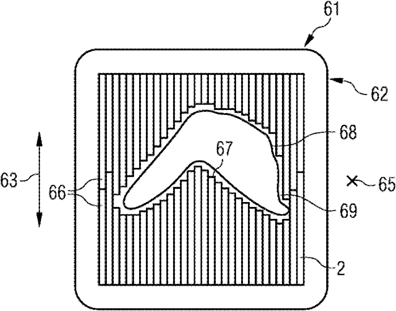
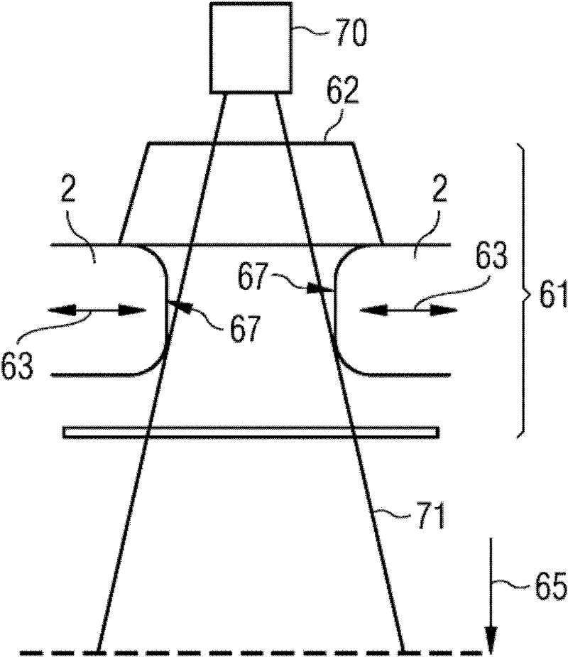
[0035] figure 1 with figure 2 The principle of a multi-leaf collimator is shown, in which the beam is shaped according to the region to be irradiated by means of the leaves. Current multi-leaf collimators have, for example, 80 leaves or lobes each with a thickness of 0.5 cm on both sides.

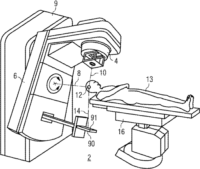
[0036] image 3 An illumination system with an electronic portal imaging device is shown.

[0037] Figure 4 A first step in the calibration according to the invention is shown. What is involved in this first step is that the multi-leaf collimator and the plate of the EPID do not have to be aligned with each other in direction, ie both the multi-leaf collimator and the plate may be twisted relative to each other or may form an angle. In order to compensate for or take into account the lack of coordination in this direction, the processing takes place as shown in the figure. The first acquisition is made in the direction of the multi-leaf collimator (here marked 90°). In this recordi...


PUM


Abstract

The invention relates to a method for calibrating a multileaf collimator by determining a value for a drift of a position of a collimator leaf carriage. The method comprises the steps of: a) defining a reference position of the collimator leaf carriage; b) determining a first value for a drift of a first position of a leaf from a first defined absolute position, the leaf being arranged on the collimator leaf carriage and the collimator leaf carriage being located at the reference position; c) moving the collimator leaf carriage to a position to be checked; d) determining a second value, the second value being for a drift of a second position of the leaf from a second defined absolute position, the collimator leaf carriage being located at the position to be checked; e) determining a difference value by forming the difference between the first value and the second value for the drift of the position of the leaf; and f) using the difference value as a value for the drift of the position of the collimator leaf carriage for the position to be checked.

Description

technical field [0001] The invention relates to a method for calibrating a multi-leaf collimator. Background technique [0002] So-called multileaf collimators (or multileaf collimators) (often abbreviated to MLC) are used for beam shaping in radiotherapy. Such a collimator comprises a large number of blades which can be moved independently of each other, so that in this way the radiation field can be flexibly adjusted. As a rule, the beam is limited in this way to the relevant tissue to be irradiated. [0003] figure 1 with figure 2 It is schematically shown how to define an irradiation region (ROI, Region of Interest) by means of a multi-leaf collimator. The multi-leaf collimator 61 has a housing 62 and leaves 2 which are adjustable in a movement direction 63 by means of an adjustment mechanism. The adjustment mechanism is housed in the housing 62 . The blade 2 absorbs the rays of the beam 71 emitted by the radiation source 70 ( figure 2 ). Radiation direction 65...

Claims


Application Information

Patent Timeline
Patent Type & Authority Applications(China)
IPC IPC(8): A61N5/00G21K1/02
CPCA61N5/1045G21K1/046A61N5/1048A61N5/1075G21K1/04
Inventor C.艾琳菲尔德M.科勒
Owner SIEMENS AG
Why Eureka
Try Eureka