Hole flanging method and die for forming high flange on thin plate

A flange and die technology, applied to metal extrusion dies and other directions, can solve the problems of not widely used, easy to break, easy to jump out of the die surface, etc., to achieve the effect of simple die structure, improve processing efficiency, and avoid potential safety hazards.

Inactive Publication Date: 2012-07-04
深圳亿和模具制造有限公司
View PDF6 Cites 8 Cited by
  • Summary
  • Abstract
  • Description
  • Claims
  • Application Information

AI Technical Summary

Problems solved by technology

The former hole turning method is to punch a small hole in the sheet metal in advance, and then turn the hole at the next station. This is the most commonly used process method, but the height of the hole turning flange processed by this process has certain limitations, because Pre-piercing will flush out part of the material, so less material is used to extrude the hole, which affects the height of the flange formed by the hole
When the thickness of the sheet metal material is thin, the straight height of the hole flange will be greatly restricted
Although the purpose of increasing the flange height after turning over can be achieved by reducing the aperture of the pre-punching hole, the stamping needle that is too small is easy to break when punching the sheet, which is not conducive to mass production; and the pre-punching is small The waste produced by the hole is small, and it is easy to jump out of the die surface, causing the sheet metal to be crushed
And the second method of directly turning the hole at one time, because the sheet metal material is directly torn, the turned-out flange will be uneven, and there will be very sharp corners on the edge, which is easy to use and carry. Stab people, so the application is not too wide

Method used


Image

  • Hole flanging method and die for forming high flange on thin plate
  • Hole flanging method and die for forming high flange on thin plate
  • Hole flanging method and die for forming high flange on thin plate

Examples


Embodiment Construction

[0023] The present invention will be described in detail below in conjunction with the accompanying drawings.

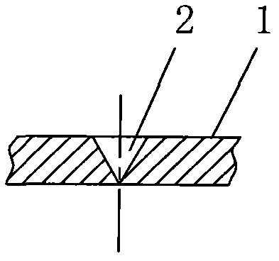
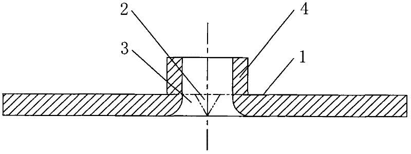
[0024] Such as figure 1 with figure 2 As shown, the hole-turning method of the present invention has no waste material generation, and the straight body height of the flange 4 formed by the hole-turning is very high, and the edge of the flange 4 will not produce sharp sharp angles. The method comprises the following steps: A, extruding Pressure cone hole: the cone hole 2 is vertically extruded on the sheet metal base material 1. During the extrusion process, as the cone hole 2 gradually expands, the metal material at the extruded part produces plastic deformation and flows to the cone hole 2 to form a accumulation area 3. The conical hole 2 formed by the final extrusion should not pierce the sheet metal base material 1, so as to avoid the generation of waste; B. Reverse turning hole: from the back of the sheet metal base material 1 to the corresponding position of ...


PUM


Abstract

The invention discloses a hole flanging method and dies for forming a high flange on a thin plate. The hole flanging method comprises the following steps of: extruding a taper hole, flanging the hole reversely and setting molding, namely extruding the taper hole which does not pierce a sheet metal, flanging the taper hole reversely, and drawing to form a high flange which is subjected to the hole flanging. According to the dies for forming the high flange on the thin plate, hole prepressing and hole flanging can be performed by using two sets of dies, and disposable hole prepressing and hole flanging also can be performed by using a set of dies. According to the hole flanging method and the dies, scrap materials are avoided, the height of the flange formed by the hole flanging is high, and the extruded taper hole can prevent materials from cracking during post-hole flanging, so that a pointed sharp corner is not formed at the margin of the flange which is subjected to the hole flanging, and potential safety hazards are avoided; a production mode is flexible, namely the flange can be formed by two-time hole flanging and also can be formed directly by one-time hole flanging; and the dies for the process have a simple structure, so that the improvement of the machining efficiency is facilitated.

Description

【Technical field】 [0001] The invention relates to a hole turning process, in particular to a hole turning method and a mold for forming a high flange on a thin plate. 【Background technique】 [0002] In the stamping industry, hole turning processing is often performed on sheet metal. Hole turning refers to a stamping method that uses a mold to turn the edge of the hole on the sheet metal into a flange (vertical straight edge). Turning holes is mainly used on sheet metal. Fasten the screws and rivet the two sheets together. There are two kinds of processing methods for the existing hole turning process: one is the turning hole formed in two times, which first pre-punches the small hole with the pre-punching mold, and then uses the hole turning mold to turn the hole; the other is directly bursting One-time punching of the sheet. The former method of turning holes is to punch a small hole in the sheet metal in advance, and then turn the hole at the next station. This is the mo...

Claims


Application Information

Patent Timeline
Patent Type & Authority Applications(China)
IPC IPC(8): B21C23/18B21C23/20B21C25/02B21D22/20
Inventor 张文兵
Owner 深圳亿和模具制造有限公司
Why Eureka
Try Eureka