Cooling and lubricating device of hot-extrusion male die

A cooling lubrication and lubricating device technology, which is applied in the field of punch lubricating and cooling devices, can solve the problems of no lubrication, easy cracks, upsetting and other problems of punches, and achieve the effects of delaying temperature rise, reducing deformation force and long service life

Inactive Publication Date: 2012-07-04
襄阳中铁宏吉工程技术有限公司
View PDF6 Cites 9 Cited by
  • Summary
  • Abstract
  • Description
  • Claims
  • Application Information

AI Technical Summary

Problems solved by technology

[0002] At present, the cooling method adopted by the punch in the process of hot extrusion is generally: (1) Cooling from top to bottom: cooling water flows down from the upper part of the punch, first cooling the lower temperature part of the punch, and then cooling the higher temperature part , the cooling water cools from top to bottom, and the water gets hotter as it goes down. When it reaches the lower part, a large amount of steam will be generated around the punch, forming a layer of steam diaphragm. Due to the high production speed, the most heated parts often cannot be fully cooled in time. , leading to higher and higher temperatures on the end surface of the punch, which is easily upset; at the same time, the temperature of the upper part of the punch itself is lower, and it is cooled first, and the temperature difference between the lower part and the lower part is large, and the punch is easily broken; (2) Cooling with a large amount of water spray : There is a lot of water left on the operating table. For relatively small workpieces, the temperature of the workpiece is greatly reduced. At the same time, the sprayed lubricant is also washed away by the water. The punch is almost not lubricated. At the same time, the cooling is too intense, and some hot molds The material is prone to cracks, and the service life of the punch is relatively low; (3) The center of the punch is cooled by circulating water: for a punch with a larger diameter, water can be added to the inside of the punch for cooling; for a small punch, the size of the punch itself is small, Opening holes to pass water inside has a great influence on the strength of the punch

Method used


Image

  • Cooling and lubricating device of hot-extrusion male die
  • Cooling and lubricating device of hot-extrusion male die
  • Cooling and lubricating device of hot-extrusion male die

Examples


Embodiment Construction

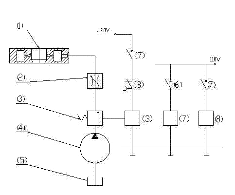
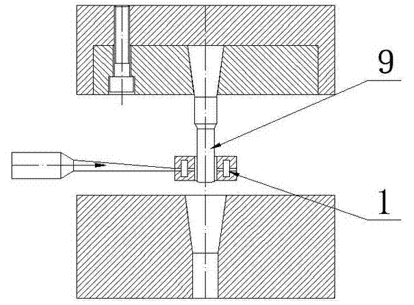
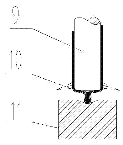
[0011] Such as figure 1 , 2 , shown in 3, lubricant nozzle of the present invention is to adopt ring nozzle 1, and the bottom of ring nozzle 1 is inverted conical, and the following is small, and the top is big, and nozzle 1 inner wall is provided with aperture, and aperture is in the form of horizontal plane. Arranged upward at a certain angle; the lubricant is extracted from the lubricant storage tank 5 through the water pump 4, flows into the annular nozzle 1 through the pipeline through the electronically controlled on-off valve 3 and the throttle valve 6, and passes through the inner ring wall of the annular nozzle 1 Evenly distributed small holes are sprayed out and sprayed on the punch 9. Due to the fast injection speed, the lubricant meets the steam diaphragm formed by the red hot punch 9 and is instantly destroyed, and the punch 9 can be cooled rapidly; The contact time between the end surface and the workpiece 11 is the longest and the temperature is the highest. Si...


PUM


Abstract

The invention relates to a cooling and lubricating device of a hot-extrusion male die in a hot-extrusion process, in particular to a cooling and lubricating device of a male die in small and deep hole extrusion, which is mainly used for solving the problem that in the hot-extrusion process, a large amount of ejected water for cooling the male die can thoroughly cool the male die, but the temperature is too low and service life can be shortened, and in a fast continuous extrusion process, lubricants cannot be ejected on the male die fast, a punch head is seriously abraded, and service life is short. The cooling and lubricating device adopts an annular nozzle to be sequentially connected with a throttle valve, an electric control on-off valve, a water pump and a lubricant box through pipelines, and the electric control on-off valve is connected with an auxiliary switch for controlling the electric control on-off valve to be on and off. The cooling and lubricating device adopts spraying from down to top, ensures temperature of the male die not to be overlow by controlling flow of the lubricants, spraying time and positions, leads the lubricants to be left on the male die evenly and form a protection layer on the male die, accordingly delays temperature rising of the male die and prolongs service life of the male die.

Description

technical field [0001] The invention relates to a punch lubricating and cooling device in the hot extrusion process. Especially the cooling and lubrication of the punch during hot extrusion of small deep holes. Background technique [0002] At present, the cooling method adopted by the punch in the process of hot extrusion is generally: (1) Cooling from top to bottom: cooling water flows down from the upper part of the punch, first cooling the lower temperature part of the punch, and then cooling the higher temperature part , the cooling water cools from top to bottom, and the water gets hotter as it goes down. When it reaches the lower part, a large amount of steam will be generated around the punch, forming a layer of steam diaphragm. Due to the high production speed, the most heated parts often cannot be fully cooled in time. , leading to higher and higher temperatures on the end surface of the punch, which is easily upset; at the same time, the temperature of the upper ...

Claims


Application Information

Patent Timeline
Patent Type & Authority Applications(China)
IPC IPC(8): B21C23/32B21C29/04
Inventor 易爱军金建铭陈良保
Owner 襄阳中铁宏吉工程技术有限公司
Why Eureka
Try Eureka