Apparatus for manufacturing a carrier tape and method for manufacturing a carrier tape

A technology for manufacturing devices and manufacturing methods, applied in the direction of manufacturing tools, belts, metal processing, etc., capable of solving problems such as deformation of the concave portion 302a

Active Publication Date: 2014-09-24
MURATA MFG CO LTD
View PDF7 Cites 0 Cited by
  • Summary
  • Abstract
  • Description
  • Claims
  • Application Information

AI Technical Summary

Problems solved by technology

like Figure 8 As shown, when the concave portion 302a temporarily formed on the surface of the base material 301 by the comb blade 202 located in the front row in the arrow A direction is compressed again using the comb blade 202a located in the last row in the arrow A direction, the The row of combs 202a shaves off a portion 303 of the recess 302a, thereby possibly deforming the shape of the recess 302a

Method used


Image

  • Apparatus for manufacturing a carrier tape and method for manufacturing a carrier tape
  • Apparatus for manufacturing a carrier tape and method for manufacturing a carrier tape
  • Apparatus for manufacturing a carrier tape and method for manufacturing a carrier tape

Examples


Embodiment approach 1

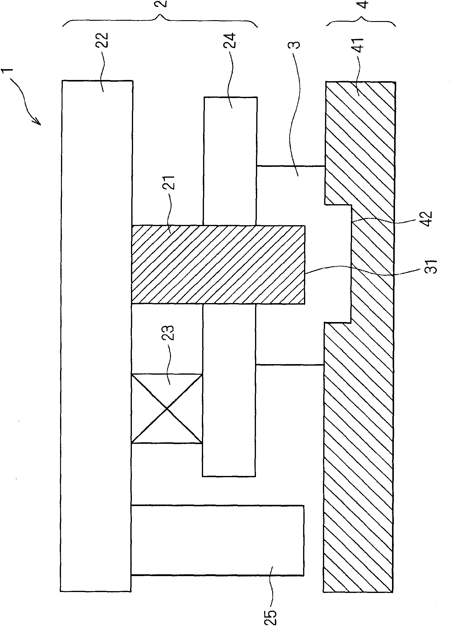
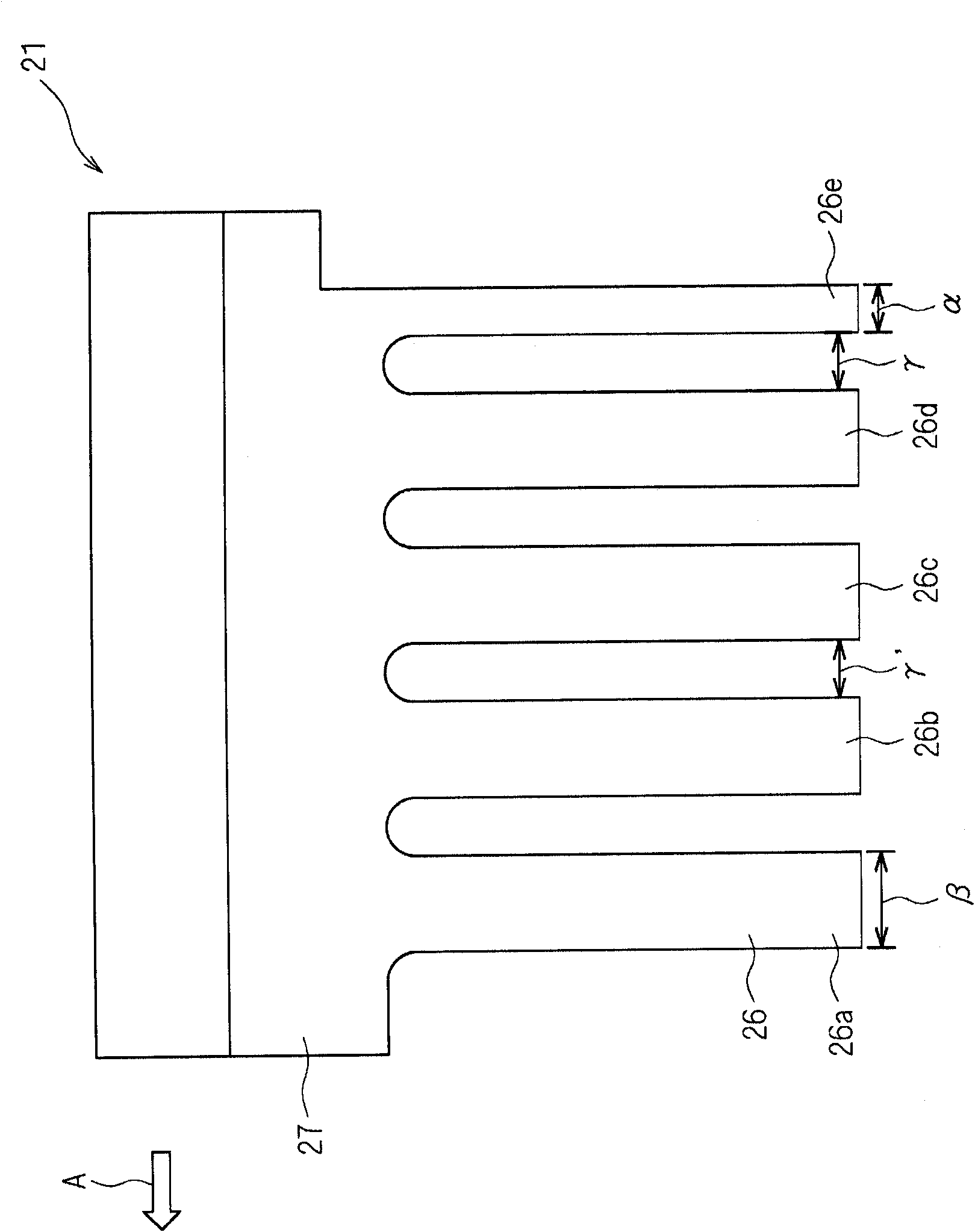
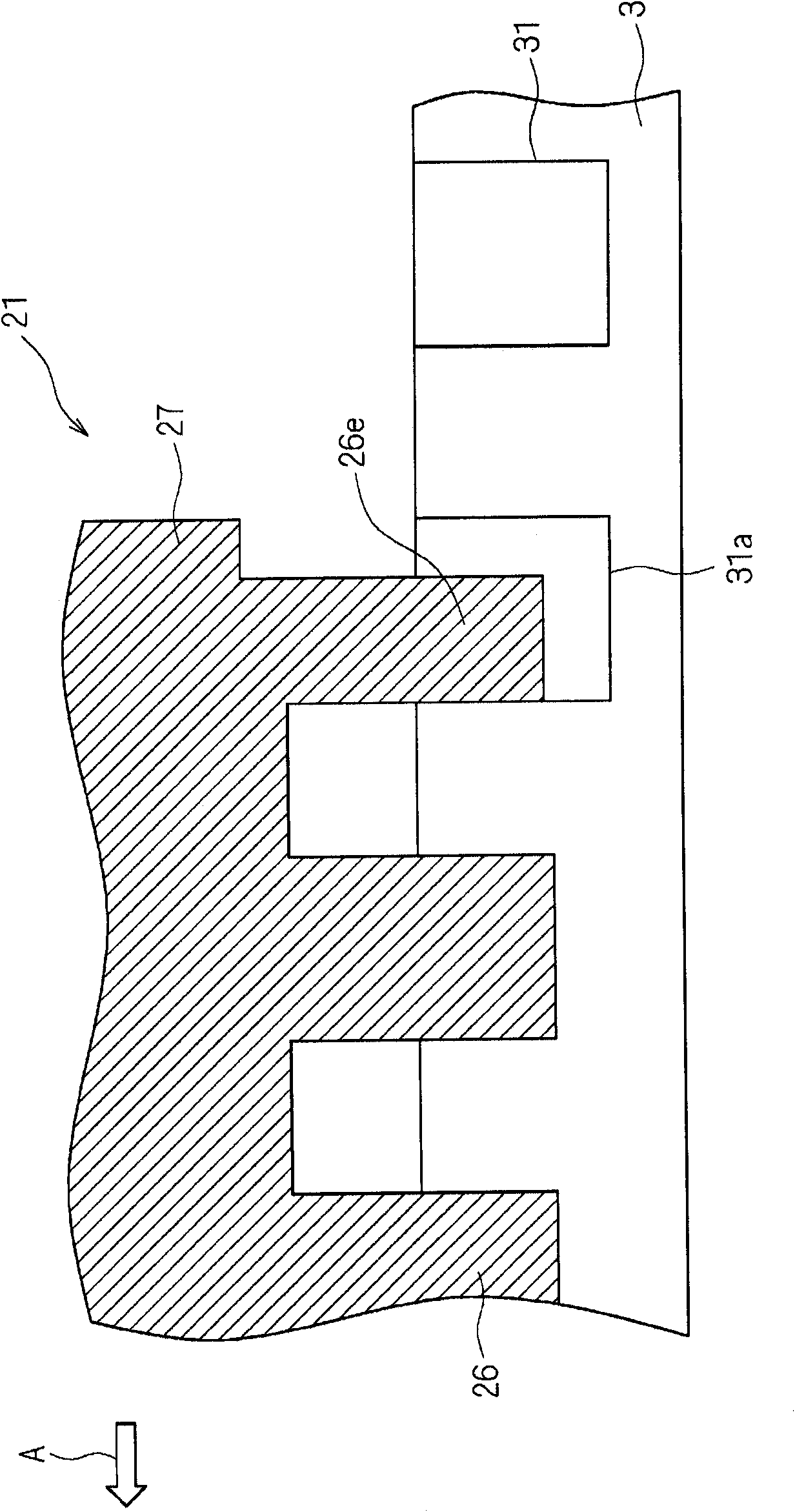
[0050] figure 1 It is a cross-sectional view when seeing the cope box and the drag box of the carrier tape manufacturing apparatus according to Embodiment 1 of the present invention from the side direction. figure 1 The illustrated carrier tape manufacturing apparatus 1 includes a cope (first mold) 2 and a drag (second mold) 4 fitted with the cope to compression-mold a base material 3 . The cope box 2 has a punch 21 forming a plurality of recesses 31 for storing electronic components on the surface (one side) of the strip-shaped base material 3, a punch holder 22 for holding the punch 21, and a Spring 23 and the stripping plate 24 that is connected with punch seat 22. strip substrate 3 to be perpendicular to the figure 1 The conveyed substrate 3 is conveyed with a predetermined pitch in the direction of the paper surface, and the conveyed base material 3 is compression-molded with a punch 21 to form the recesses 31 . The release plate 24 is a member that presses the base...

Embodiment approach 2

[0059] The structure of the punch used in the carrier tape manufacturing apparatus 1 according to Embodiment 2 of the present invention will be described. In the structure of the punch, the width in the direction of arrow A of the comb positioned in the rearmost row or the width in the direction of arrow A is not changed. The dimension in the orthogonal direction can make the shape of the concave portion less likely to be deformed when the concave portion temporarily formed by the comb blade located in the front row is compressed again using the comb blade located in the rearmost row. Figure 5 It is a front view of a punch used in the carrier tape manufacturing apparatus 1 according to Embodiment 2 of the present invention. Since the structure of the carrier tape manufacturing apparatus 1 other than the punch 51 is the same as the structure of the carrier tape manufacturing apparatus 1 of Embodiment 1, detailed description is abbreviate|omitted.

[0060] Figure 5 The punch ...


PUM


Abstract

PROBLEM TO BE SOLVED: To provide a device for manufacturing a carrier tape including a comb-shaped punch reducing a possibility of deforming a shape of a recess when the recess formed once by a comb blade located at a top in a direction of the relative displacement of the punch with respect to a carrying direction of a substrate is compressed again by a comb blade located at a trail end in the direction of the relative displacement of the punch with respect to the carrying direction of the substrate, and a method of manufacturing the carrier tape.SOLUTION: The device 1 for manufacturing the carrier tape includes: an upper die 2 including the punch 21 forming a plurality of recesses 31 for storing electronic components on the surface of the substrate 3; and a lower die 4 on which the substrate 3 is placed and which is fitted to the upper die 2 to compress and form the substrate 3. The punch 21 includes a plurality of comb blades 26 arranged to form a line. An area of a face compressing the substrate 3 of the comb blade 26e located at the trailing end in the direction of the relative displacement of the punch 21 with respect to the carrying direction of the substrate 3 is set smaller than those of the other comb blades 26a-26d.

Description

technical field [0001] The present invention relates to a carrier tape manufacturing device and a method for manufacturing a carrier tape, and in particular, to a carrier tape that compresses and molds a conveyed strip-shaped substrate to manufacture a concave portion for housing electronic components. The carrier tape manufacturing device and the manufacturing method of the carrier tape. Background technique [0002] In an apparatus for mounting electronic components on a circuit board, a carrier tape containing electronic components is used in order to easily supply the electronic components. Patent Document 1 discloses a conventional carrier tape manufacturing apparatus. [0003] Patent Document 1 discloses an apparatus for manufacturing a carrier tape by compression-molding a strip-shaped substrate conveyed by a cope and a drag, wherein the cope has a punch forming a carrier tape. A plurality of recesses are used to accommodate electronic components, and the above-ment...

Claims


Application Information

Patent Timeline
Patent Type & Authority Patents(China)
IPC IPC(8): B21D53/14B21D37/00
CPCB26F1/40B26F1/44B26F2001/4472H05K13/0417
Inventor 床井正护清水保弘
Owner MURATA MFG CO LTD
Why Eureka
Try Eureka