steel bar bending machine

A hoop bending machine and steel bar technology, applied in the field of steel bar hoop bending machines, can solve the problems of high manufacturing precision, complicated equipment, labor intensity of time-consuming and laborious workers, etc., and achieve the effect of improving work efficiency, good dimensional consistency, and reducing labor intensity.

Active Publication Date: 2015-09-09
贵州建工集团第四建筑工程有限责任公司
View PDF6 Cites 0 Cited by
  • Summary
  • Abstract
  • Description
  • Claims
  • Application Information

AI Technical Summary

Problems solved by technology

[0002] The construction industry uses a large number of stirrups formed by bending hoops, but at present, the bending hoops of steel bars are still realized by manual and automatic bending. The bending hoop mechanisms used are all positioned and clamped at one time. Another bend, time-consuming and labor-intensive, each re-clamping and positioning will cause accumulated errors, affect the quality of the stirrup forming, unstable, time-consuming and labor-intensive, and labor-intensive
Numerical control hoop bending machines have also appeared in recent years. This hoop bending machine is expensive and not suitable for most construction sites; a kind of steel bar bending hoop machine disclosed by the Chinese Patent Office on March 31, 2010, No. 200810121146.6, adopts The multi-stage cam independently controls the hoop bending mechanism at the same time, and the rotating shaft drives multiple sets of cams to rotate for a circle, and the hoop is formed immediately, but this machine is not suitable for steel bars over 2 meters or thicker steel bars; there is also a steel hoop bending machine, Three sets of crank-link mechanism are used as the bending mechanism to cooperate with the limit mechanism to realize the one-time positioning and forming of the stirrup, but the equipment is relatively complicated, the manufacturing precision is high, and the cost is high.

Method used


Image

  • steel bar bending machine
  • steel bar bending machine
  • steel bar bending machine

Examples


Embodiment Construction

[0018] The present invention will be further described below in conjunction with the accompanying drawings.

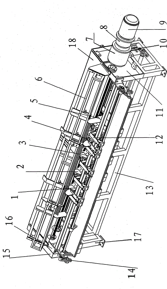
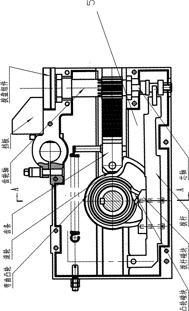
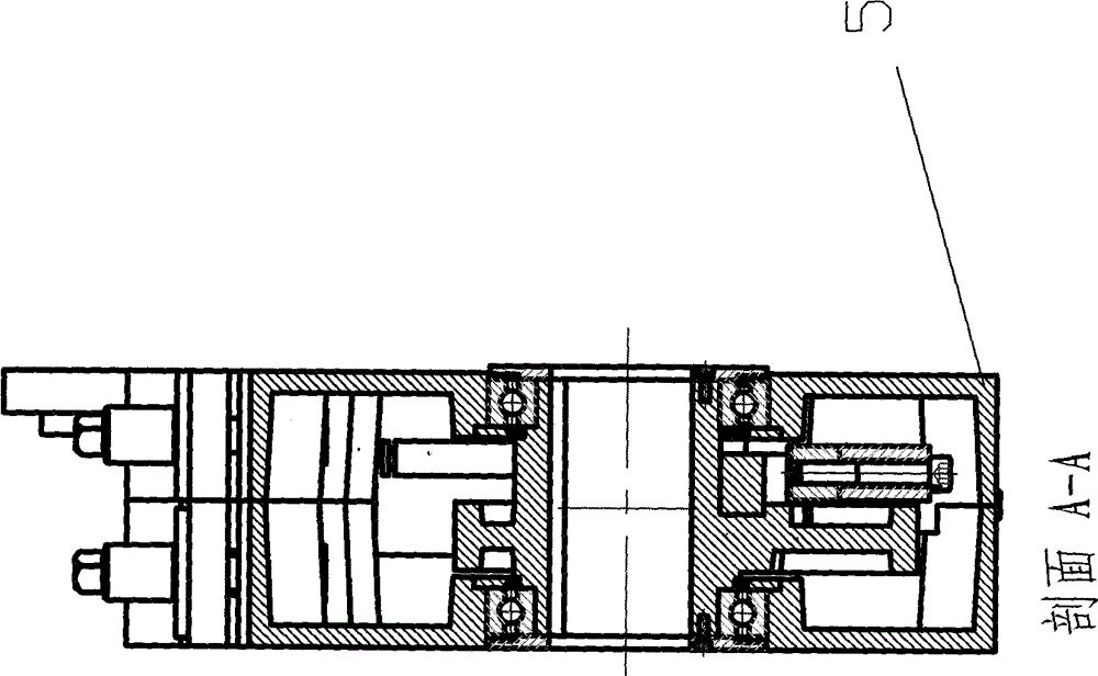
[0019] A steel hoop bending machine according to the present invention comprises: a left chassis, a middle chassis 3, a right chassis, a discharge rack assembly 6, a clutch box 7, a reducer 8, a motor 9, a pedal clutch assembly 10, and a right end plate 11 , binder plate 12, front beam assembly 13, cam swing rod assembly 14, protective cover 15, left end plate 16, frame 17, upper cover plate 18, bending cam 19, roller 20, rack 21, rack return spring 22 , Hollow gear shaft 23, mandrel 24, dial assembly 25, cam bumper 26, lever bumper 27, lever 28, dial slot 29, damping pad 30, adjustment nut 31, adjustment screw 32, adjustment rod 33. Flat pin 34, rotating arm 35, dial 36, and baffle 37, characterized in that: the left and right parts of the frame 17 are combined and assembled, the top has an upper cover 18, and both ends are equipped with a left end plate 16 and a righ...


PUM


Abstract

The invention discloses a rebar hoop bending machine, which comprises a left machine box, a middle machine box, a right machine box, an emptying frame assembly, a clutch box, a speed reducer, a motor, a pedal clutch assembly, a right end plate, a material pressing plate, a front beam assembly, a swing rod assembly and a machine frame. The left part and the right part of the machine frame are assembled in combined mode, a left end plate and the right end plate are arranged at two ends of the machine frame, the middle machine box is fixed in the middle of the interior of the machine frame, the left machine box and the right machine box are positioned on two sides of the middle machine box, the clutch box, the speed reducer and the motor are assembled at ends of a transmission shaft on the right end plate, the emptying frame assembly is arranged on the machine frame, an emptying tank is positioned above the machine box, the pedal clutch is arranged at the lower portion of the right end plate, and the let end plate is provided with the cam swing assembly. The left machine box, the middle machine box and the right machine box are all composed of bending cams, idler wheels, racks, rack return springs, hollow gear shafts, core shafts arranged in shaft holes of the hollow gear shafts and coaxial with the hollow gear shafts, poking plate assemblies, cam crash blocks, poking rod crash blocks and poking rods. A driving transmission shaft of a bending cam horizontally penetrates through bearing holes of all bending cams and horizontally penetrates through the left machine box, the middle machine box and the right machine box. The core shafts and the return springs are positioned in the hollow gear shafts. A poking fork groove, a shock pad and an adjusting nut are arranged at the lower end of the core shaft capable of being pulled. The rebar hoop bending machine is stable in quality, good in size uniformity of bended finished products and capable of improving work efficiency, reducing labor intensity of workers and simultaneously saving energy and man power.

Description

technical field [0001] The invention relates to a hoop bending machine used in the construction industry, in particular to a steel bar hoop bending machine. Background technique [0002] The construction industry uses a large number of stirrups formed by bending hoops, but at present, the bending hoops of steel bars are still realized by manual and automatic bending. The bending hoop mechanisms used are all positioned and clamped at one time. Another bend is time-consuming and labor-intensive, and each re-clamping and positioning will cause accumulated errors, which will affect the quality of the stirrup forming, unstable, time-consuming and labor-intensive for workers. Numerical control hoop bending machines have also appeared in recent years. This hoop bending machine is expensive and not suitable for most construction sites; a kind of steel bar bending hoop machine disclosed by the Chinese Patent Office on March 31, 2010, No. 200810121146.6, adopts The multi-stage cam in...

Claims


Application Information

Patent Timeline
Patent Type & Authority Patents(China)
IPC IPC(8): B21F1/00
Inventor 姚志刚李小峰刁川郭彬郑祥特
Owner 贵州建工集团第四建筑工程有限责任公司
Why Eureka
Try Eureka