Spring winding device of lathe

A forming device and winding technology, applied in the field of forming devices for lathe winding springs, can solve the problems of long auxiliary time for cutting steel wires, and achieve the effects of low labor intensity of workers, shortened auxiliary time, and simple structure

Inactive Publication Date: 2012-07-04
SHAOGUAN CITY INST OF TECHNICIAN
View PDF5 Cites 13 Cited by
  • Summary
  • Abstract
  • Description
  • Claims
  • Application Information

AI Technical Summary

Problems solved by technology

[0003] The object of the present invention is to provide a new type of forming device for lathe winding springs, which relates to a device for processing steel wires into springs on a lathe. Solve the problem of long auxiliary time for manually cutting steel wires one by one on the basis of

Method used


Image

  • Spring winding device of lathe
  • Spring winding device of lathe
  • Spring winding device of lathe

Examples


Embodiment Construction

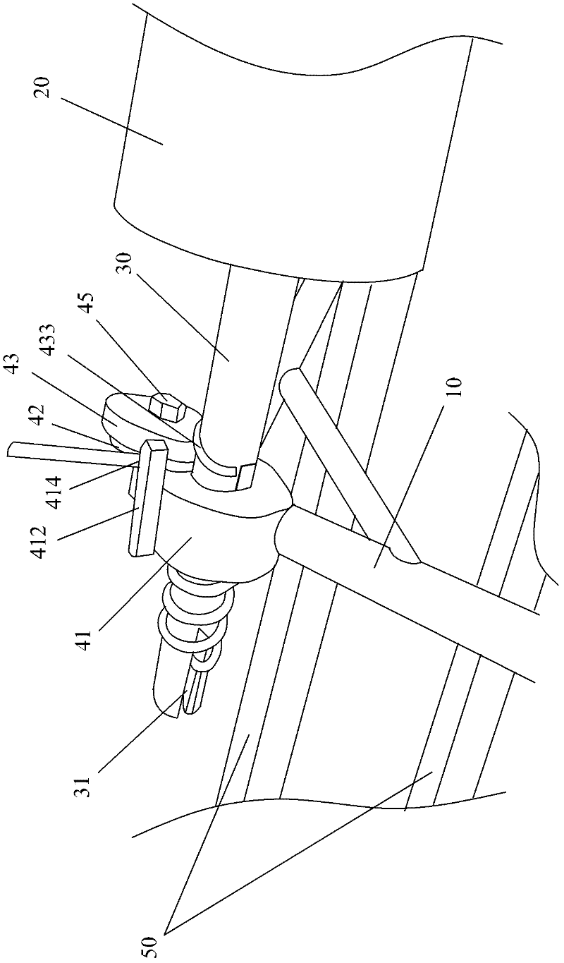
[0025] see Figure 1~3 As shown, the structure of the lathe spring winding forming device of the present invention includes: a frame bar 10, a lathe spindle 20, a mandrel 30 installed on the lathe spindle 20, a forming mechanism 40, and a lathe bed guide rail 50, etc. The mandrel 30 is driven to rotate by the chuck (not shown in the figure) of the lathe spindle 20, and the steel wire is bent and formed into a spring. The forming mechanism 40 is fixed on the frame bar 10 , one end of the mandrel 30 is clamped on the chuck of the lathe spindle 20 , and the other end of the mandrel 30 is matched with the forming mechanism 40 . The end of the mandrel 30 used for spring forming is provided with a slot 31 (the radial opening groove at the extension end of the mandrel 30), the end of the steel wire can be inserted into the slot 31, and the bending of the mandrel 30 , and the remaining steel wire sections are just wound on the mandrel 30 until the end.

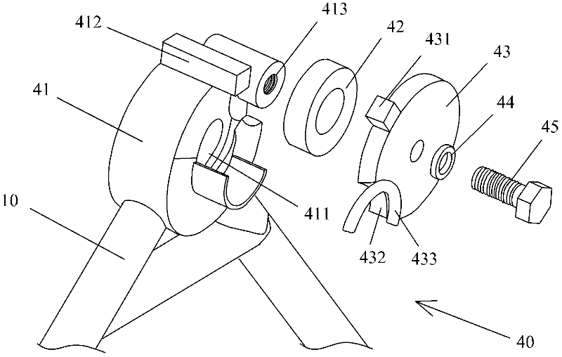
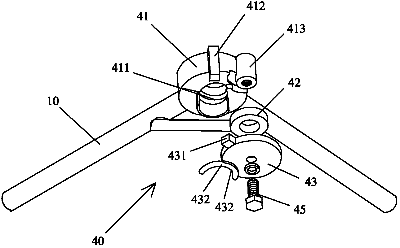
[0026] like figure 2 and ...


PUM


Abstract

The invention discloses a spring winding device of a lathe, which comprises a rest rod, a forming mechanism and a mandrel. The forming mechanism is mounted on the rest rod, the mandrel is connected with the forming mechanism and mounted on a chuck of a spindle of the lathe, the other end of the mandrel is connected to the forming mechanism, the mandrel is driven to rotate by the chuck of the spindle of the lathe, and the forming mechanism is used for winding steel wires to form springs. The forming mechanism, fixing bolts, a guide wheel, the mandrel and the rest rod of the spring winding device lay foundation for forming springs by using long steel wires. The spring winding device has the advantages of high efficiency, economical effect, environmental protection, low labor intensity of workers, accurate pitch control, simple structure and low manufacturing cost. Besides, the spring manufacturing process is completed on the lathe by the spring winding device so that manufacturing cost is saved greatly. Since the spring winding device is provided with the nuts of the fixed pitch, the pitch of the springs manufactured by the same can be controlled well and the spring winding device of the lathe has long service life.

Description

technical field [0001] The invention relates to a spring forming device, in particular to a forming device for spring winding on a lathe. Background technique [0002] The existing processing device for spring forming is to install the threaded mandrel on the lathe spindle, fix one end of the steel wire to one end of the mandrel through a snap ring, then fix the other end of the steel wire with a wooden clip, and run it along the mandrel. The thread is rotated. The disadvantages of using this method to make springs are: two people are required to work together at the same time, the labor intensity is high, the machining accuracy of the spring is low, and the spring pitch control is not accurate. Cutting, auxiliary working hours are long, efficiency is low, wooden clips are easily damaged, production cost is high, and it is not environmentally friendly. Contents of the invention [0003] The object of the present invention is to provide a new type of forming device for lat...

Claims


Application Information

Patent Timeline
Patent Type & Authority Applications(China)
IPC IPC(8): B21F3/06
Inventor 廖卓兴
Owner SHAOGUAN CITY INST OF TECHNICIAN
Why Eureka
Try Eureka