Hydraulic location device for guiding ship in floating dock and working method thereof

A technology of hydraulic positioning and working method, applied in dry dock, transportation and packaging, ships, etc., can solve the problems of slow traction speed, low operation efficiency, occupying the usable area of ​​the dock wall deck, etc., and achieve simple mechanism, simple operation and installation. handy effect

Active Publication Date: 2012-07-04
DALIAN UNIV OF TECH
View PDF7 Cites 5 Cited by
  • Summary
  • Abstract
  • Description
  • Claims
  • Application Information

AI Technical Summary

Problems solved by technology

This process has the following disadvantages: first, the precision of the flexible steel cable towing the ship is low, the pulling speed is very slow, and the operation efficiency is low; second, if the dock wall of the floating dock is not continuous, the pilot trolley cannot be installed; The trolley, track and traction system are continuously laid along the dock wall of the floating dock from front to back, occupying the usable area of ​​the deck of the dock wall; fourth, the pilot trolley can only be used for traction of ships floating into the floating dock, and cannot be used for floating docks and docks Plane docking transportation, nor can it be used as auxiliary fastening measures for floating dock sea towing transportation

Method used


Image

  • Hydraulic location device for guiding ship in floating dock and working method thereof
  • Hydraulic location device for guiding ship in floating dock and working method thereof
  • Hydraulic location device for guiding ship in floating dock and working method thereof

Examples


Embodiment Construction

[0026] The structure of the present invention will be further described below with reference to the accompanying drawings.

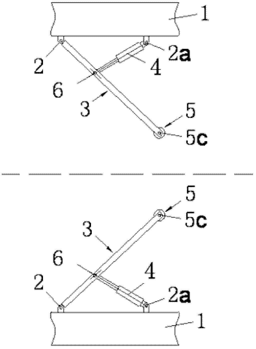
[0027] figure 1 Shown is the layout of the hydraulic positioning device used for piloting the floating dock. In the figure, this hydraulic positioning device for piloting ships in the floating dock includes two plane steel frames 3, two hydraulic cylinders 4 and rubber wheels 5, and the first support 2 and the second support 2a are fixed on the bulwark 1 of the floating dock. and arranged symmetrically with the center of the floating dock. One end of the plane steel frame 3 is rotatably connected to the first support 2, and the other end is provided with a rubber wheel shaft 5c. The rubber wheel 5 and the rubber wheel shaft 5 form a rotational fit. One end of it is rotatably connected with the second support 2a, and the other end is hingedly connected with the plane steel frame 3 via the hinge 6.

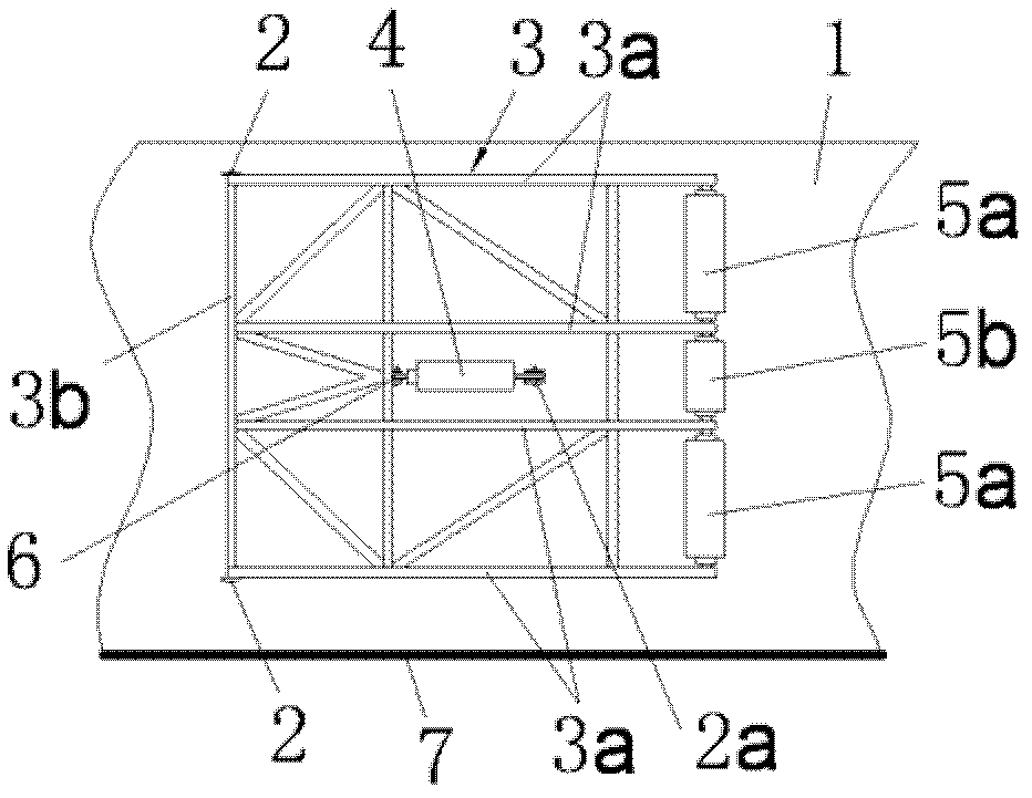
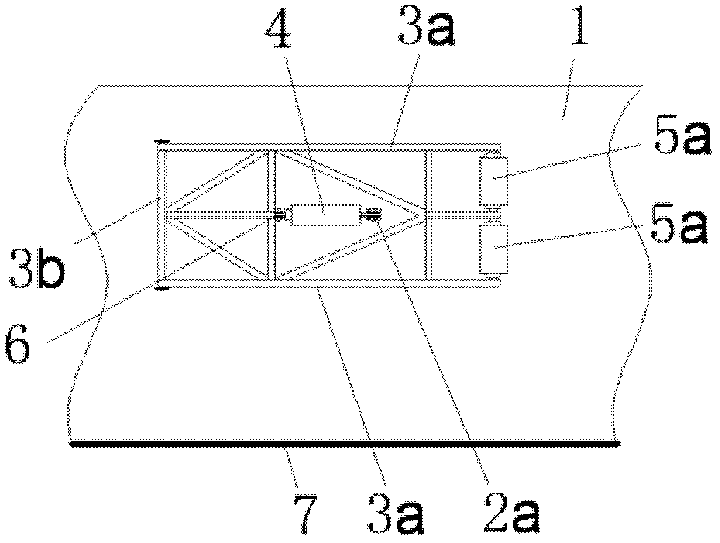
[0028] figure 2 The structure diagram of the first s...


PUM


Abstract

A hydraulic location device for guiding a ship in a floating dock and a working method thereof belong to the technical field of ship maintenance and modification and oceaneering equipment. The ship guiding location device with a hydraulic location function is composed of a plane steel frame, a rubber wheel, a hydraulic cylinder and the like. The device is installed on the inner side of two ship boards of a dock wall of the floating dock. The device can meet requirements for two kinds of docking and lying and ensure accurate lying position. The two kinds of docking and lying conditions are characterized in that the ship is guided into a dock for lying when the floating dock is submerged, or an air bag is utilized to load maritime work structural objects to enter the dock for lying when the floating dock is contacted with a wharf in abutting mode. In addition, the device has auxiliary fastening effect on products to be transported in the floating dock transportation process. The device is installed on the dock wall of the floating dock and is capable of accurately and quickly conducting safe lying location on the products entering the dock in controllable mode in the ship guiding load receiving process. The device has the advantages of being concise in mechanism, simple to operate, accurate in location, convenient to install and low in cost and also has the advantages of hydraulic program control and rigidity limit.

Description

technical field [0001] The invention relates to a hydraulic positioning device for piloting a ship in a floating dock and a working method thereof, which is a limit control device for marine engineering, ship repairing technology and marine transportation, and belongs to the technical field of ship repairing and marine engineering equipment. Background technique [0002] At present, on the dock wall of the floating dock, a dolly is usually installed, and the dolly is driven by a motor to drive a flexible steel cable to pull the ship to float into the floating dock. This process has the following disadvantages: first, the precision of the flexible steel cable towing the ship is low, the pulling speed is very slow, and the operation efficiency is low; second, if the dock wall of the floating dock is not continuous, the pilot trolley cannot be installed; The trolley, track and traction system are continuously laid along the dock wall of the floating dock from front to back, occ...

Claims


Application Information

Patent Timeline
Patent Type & Authority Applications(China)
IPC IPC(8): B63C1/02
Inventor 林焰陈明于雁云金朝光王运龙
Owner DALIAN UNIV OF TECH
Why Eureka
Try Eureka