Vessel demagnetizing method

A ship and demagnetization technology, applied to ships, ship weapons, attack devices, etc., can solve time-consuming and labor-intensive problems, achieve the effects of reducing labor intensity, improving emergency benefits, and shortening demagnetization time

Inactive Publication Date: 2012-07-04
NAVAL UNIV OF ENG PLA
View PDF5 Cites 3 Cited by
  • Summary
  • Abstract
  • Description
  • Claims
  • Application Information

AI Technical Summary

Problems solved by technology

[0003] The invention provides a ship demagnetization method, which solves the time-consuming and labor-intensive problem of the existing ship demagnetization method, and does not need to wind the demagnetization coil to meet the needs of fast demagnetization of the ship

Method used


Image

  • Vessel demagnetizing method
  • Vessel demagnetizing method
  • Vessel demagnetizing method

Examples


Embodiment 1

[0025] Embodiment 1, a ship of 2 tons class, ship width B=1.5m, midship radial circumference L=5m, the vertical component Hz=20A / m of local geomagnetic field, Hp=30A / m, realize overall Demagnetization, including the following steps:

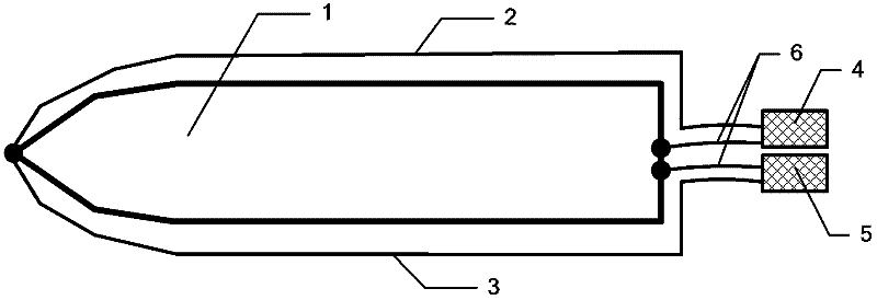
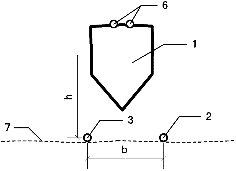
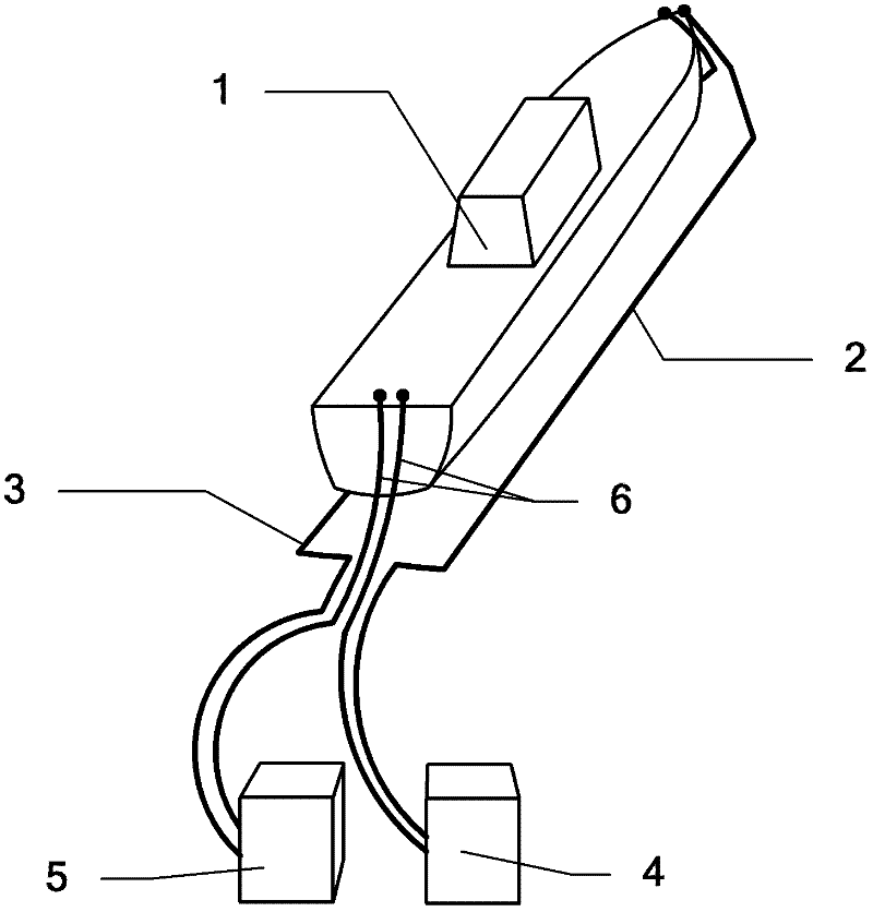
[0026] (1) Steps for laying submarine cables: such as figure 1 , figure 2 , image 3 As shown, the left side submarine cable 3 and the right side submarine cable 2 are laid in parallel along the geomagnetic east-west direction in the seabed 7 of the water depth h=2B=3m, and the interval b=2B=3m between the left side and the right side submarine cables will be demagnetized Ship 1 is moored above the left and right submarine cables, the axis of the degaussed ship is parallel to the left and right submarine cables, and the projection of the demagnetized ship axis on the seabed is located between the left and right submarine cables;

[0027] (2) Steps of forming a loop: adopt the left side pulse power supply 5 and the right side pulse power suppl...

Embodiment 2

[0033] Embodiment 2, a 2000-ton ship, the ship width B=10m, the midship radial circumference L=50m, the vertical component Hz=30A / m of the local geomagnetic field, Hp=20A / m, realize overall demagnetization , including the following steps:

[0034] (1) Steps for laying submarine cables: such as figure 1 , figure 2 , image 3 As shown, the left side submarine cable 3 and the right side submarine cable 2 are laid in parallel along the geomagnetic east-west direction in the seabed 7 of water depth h=1B=10m, and the interval b=1B=10m between the left side and the right side submarine cables will be demagnetized Ship 1 is moored above the left and right submarine cables, the axis of the degaussed ship is parallel to the left and right submarine cables, and the projection of the demagnetized ship axis on the seabed is located between the left and right submarine cables;

[0035] (2) Steps of forming a loop: adopt the left side pulse power supply 5 and the right side pulse power s...

Embodiment 3

[0042] Embodiment 3, a ship of 30000 ton class, ship width B=30m, midship radial circumference L=100m, the vertical component Hz=20A / m of local geomagnetic field, Hp=30A / m, realize overall demagnetization , including the following steps:

[0043] (1) Steps for laying submarine cables: such as figure 1 , figure 2 , image 3 Shown, in the seabed 7 of water depth h=0.5B=15m parallel laying left side submarine cable 3 and right side submarine cable 2 along geomagnetic east-west direction, interval b=0.5B=15m between left side and right side submarine cable, will The degaussed ship 1 is moored above the left and right submarine cables, the axis of the degaussed ship is parallel to the left and right submarine cables, and the projection of the demagnetized ship axis on the seabed is located between the left and right submarine cables;

[0044] (2) Steps of forming a loop: adopt the left side pulse power supply 5 and the right side pulse power supply 4 to supply power to the left...


PUM


Abstract

A vessel demagnetizing method belongs to the field of vessel demagnetization and solves the problem of time and labor consumption of existing vessel demagnetizing methods. The vessel demagnetizing method includes steps: firstly, laying submarine cables, namely laying left and right submarine cables on the sea floor, and anchoring a demagnetized vessel above the left and right submarine cables; secondly, forming a loop, namely using the cables to connecting one pole of a left pulse power source and one pole of a right pulse power source with the stern of the demagnetized vessel, and connecting the other pole of the left pulse power source and the other pole of the right pulse power source with the stem of the demagnetized vessel through the left and right submarine cables; and thirdly, electrifying for demagnetizing, namely using the left pulse power source and the right pulse power source to supply pulse current of superimposed direct-current component to the left and right submarine cables. Winding of the cables is not needed, a vessel body is directly electrified for demagnetizing, labor intensity is relieved, demagnetizing time is shortened, and expenditure is saved. Further, the vessel demagnetizing method is effective in demagnetization and low in energy consumption, the demagnetized vessel is easy in maneuvering, and the vessel demagnetizing method is especially suitable for demagnetization of a great quantity of vessels in emergency, and has fine emergency benefit and economic value.

Description

technical field [0001] The invention belongs to the technical field of ship degaussing, and in particular relates to a ship demagnetization method, which directly energizes the ship hull to eliminate the fixed magnetism of the ship body without winding coils. Background technique [0002] At present, the requirements for demagnetization of ships are getting higher and higher. Demagnetization ships (stations) widely use temporary coils to demagnetize ships. During demagnetization, a large number of demagnetization cables must be bound outside the demagnetized ship to form a demagnetization coil, which is particularly time-consuming and laborious. Even for small-tonnage ships, it takes 3 to 5 days for each ship, and because the ships are bound by cables during demagnetization, it is difficult to maneuver in an emergency, which is very dangerous. This contradiction is not obvious in normal times, but in the event of an emergency or an emergency, it will face a severe situation ...

Claims


Application Information

Patent Timeline
Patent Type & Authority Applications(China)
IPC IPC(8): B63G9/06
Inventor 郭成豹刘大明肖昌汉洪泽宏唐申生刘胜道赵文春高俊吉
Owner NAVAL UNIV OF ENG PLA
Why Eureka
Try Eureka