Fermentation tank set
A fermenter and fermented liquid technology, which is applied in the field of fermenter tanks for wine brewing, can solve the problems of insufficient transformation, inability to circulate, and inability to contact grape skins, so as to improve quality and avoid the formation of wine caps.
- Summary
- Abstract
- Description
- Claims
- Application Information
AI Technical Summary
Problems solved by technology
Method used
Image

Examples
Embodiment 1
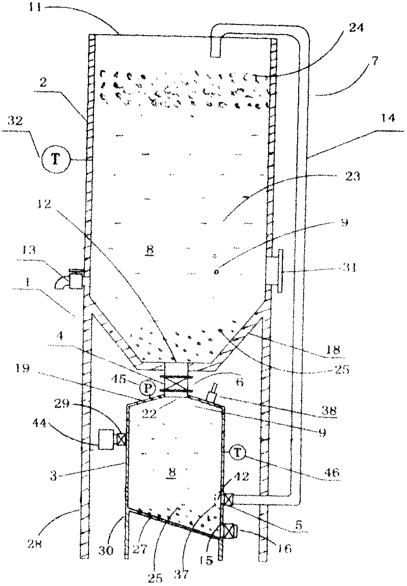
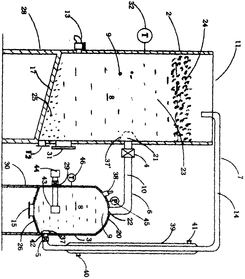
[0025] See attached figure 1 , 2 , 1 represents the entire fermenter group.
[0026] The fermentation tank group 1 of the present invention includes at least two tank bodies with a certain positional relationship and a channel connecting the two tank bodies. One of the two tank bodies is the main tank body 2, and the other tank body is the Airtight tank 3; the positional relationship between the main tank 2 and the sealable tank 3 is that the free liquid surface of the main tank 2 is higher than the free liquid surface of the sealable tank 3; the passage can make the main tank The fermentation liquid 8 in the body 2 flows into the sealable tank 3 under the action of gravity. The passage can make the gas 9 in the sealable tank 3 flow into the main tank 2, and the passage can make the sealable tank The fermentation liquid 8 in the body 3 flows into the main tank 2 under pressure.
[0027] The positional relationship between the main tank body 2 and the sealable tank body 3 is that t...
Embodiment 2
[0044] In Example 1, the channel 6 plays two roles. One is the channel for the fermentation liquid 8 in the main tank 2 to enter the sealable tank 3, and the other is for the gas 9 in the sealable tank 3 to enter the main tank 2. The channel, that is, the channel 6 is both a liquid channel and a gas channel.
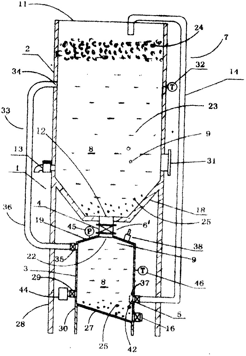
[0045] In this embodiment 2, the function of the channel 6 is separated. The channel 6 is divided into a liquid channel 6'and a gas channel 33. The liquid channel 6'enters the fermentation liquid 8 in the main tank 2 into the sealable tank. The gas channel 33 is a channel through which the gas 9 in the tank 3 can enter the main tank 2 in a sealed manner.
[0046] image 3 , Figure 4 It is the third structural deformation and the fourth structural deformation of the fermenter group of the present invention. figure 1 and figure 2 On the basis of, the function of the original channel 6 is divided into a liquid channel 6'and a gas channel 33.
[0047] An opening 34 is provided o...
Embodiment 3
[0051] In Embodiment 3, the difference from Embodiments 1 and 2 is that the fermentation liquid 8 in the sealable tank 3 in Embodiments 1 and 2 enters the main tank 2 through the channel 7, which can realize the fermentation liquid 8 in The main tank 2 and the sealable tank 3 circulate between the main tank 2 and the sealable tank 3, and the fermentation liquid 8 of the present embodiment 3 enters and exits between the main tank 2 and the sealable tank 3 through the passage 47 between the two tanks.
[0052] in Figure 5 Here, the passage is divided into at least two passages 47 and 48, and the passage 47 and the passage 48 respectively connect the main tank 2 and the sealable tank 3; the passage 47 allows The fermentation liquid 8 in the main tank 2 enters the sealable tank 3 under the action of gravity, and the passage 47 can also allow the fermentation liquid 8 in the sealable tank 3 to enter the main tank 2 under pressure; The passage 48 allows the gas 9 in the sealable tank...
PUM
 Abstract
Description
Claims
Application Information
PatSnap Eureka turns technology decisions into work you can execute. Powered by our Innovation Knowledge Graph, it runs expert workflows across engineering, life sciences, materials and intellectual property. Get your review-ready output in minutes.


