Independent pressure foot driving system of embroidering machine

A driving system and technology for embroidery machines, which are used in embroidery machines, embroidery machine mechanisms, textiles and papermaking, etc., can solve the problems of complex structure, sewing material movement, and high cost, and achieve precise movements, simplified structure, and increased pressure. Effect

Inactive Publication Date: 2012-07-04
FUJIAN YONGXIN NUMERICAL CONTROL TECH
View PDF9 Cites 12 Cited by
  • Summary
  • Abstract
  • Description
  • Claims
  • Application Information

AI Technical Summary

Problems solved by technology

[0002] Embroidery machines generally include a frame, a machine head arranged on the frame, an upper shaft arranged horizontally on the frame, a needle bar box that can be moved laterally on the machine head, and a needle bar box that can be moved up and down. A number of needle bars, a color-changing drive mechanism connected to drive the needle bar box to move laterally to select a needle bar to work, and a needle bar drive mechanism connected to drive the selected needle bar to move up and down. The traditional embroidery machine presser foot is attached to the needle bar. On the bar, a retaining ring is set on the needle bar, and the presser foot is set on the needle bar so that it can move up and down through the supporting member. The needle bar is sleeved with a presser foot spring between the retaining ring and the supporting member. The needle bar drive mechanism moves up and down, the needle bar descends, the presser foot is pressed tightly on the fabric, and the pressure is provided by the presser foot spring; The spring has low elasticity and is generally only suitable for embroidering thin materials. When embroidering thick materials and leather, the friction between the needle and the sewing material is too large. When the recovery is rising, the pressure of the presser foot is insufficient, and the fabric will be lifted by the needle. , resulting in skipped stitches, broken threads, and movement of sewing materials, etc.
In view of the above problems, there are currently an embroidery machine presser foot independent drive mechanism with a patent number of 200910113690.0 and an embroidery machine with a patent number of 200810082757.4. Both patents solve the above problems through independent drive of the presser foot, but the presser foot of the above patent The components are all set on the needle bar box, which determines that each needle bar must be equipped with a set of presser foot components, which is not only costly but also complex in structure

Method used


Image

  • Independent pressure foot driving system of embroidering machine
  • Independent pressure foot driving system of embroidering machine
  • Independent pressure foot driving system of embroidering machine

Examples


Embodiment Construction

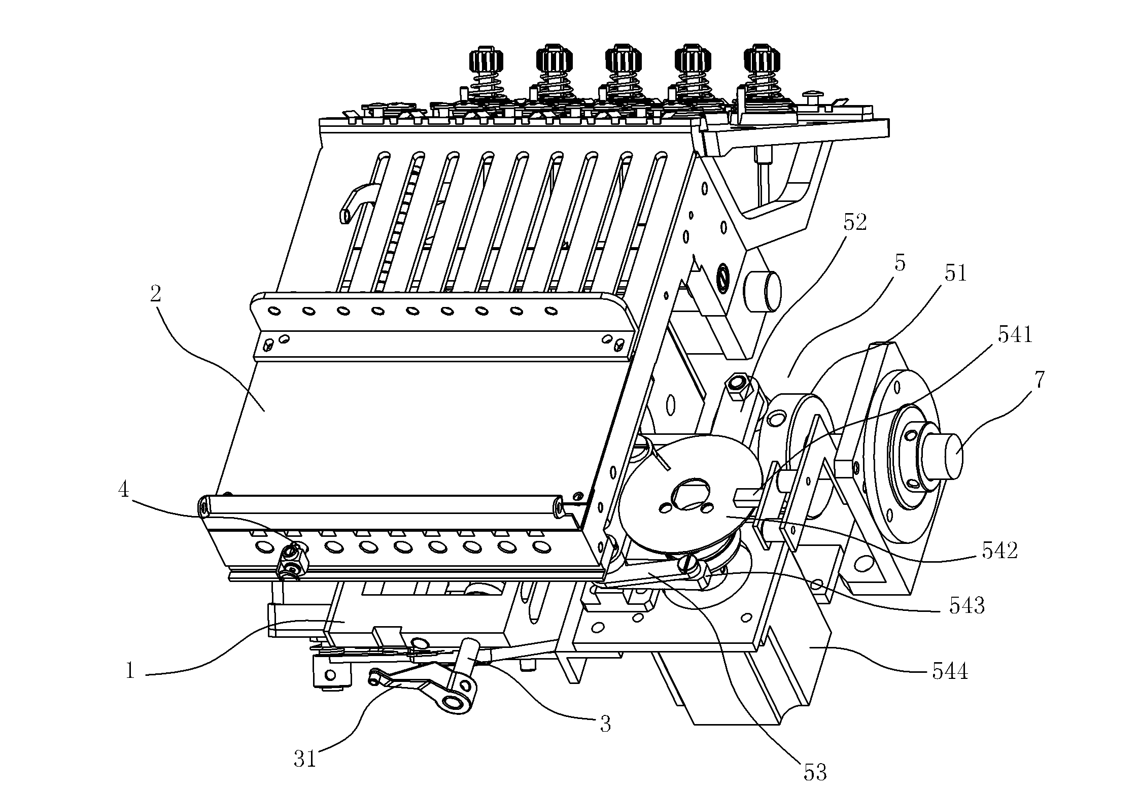
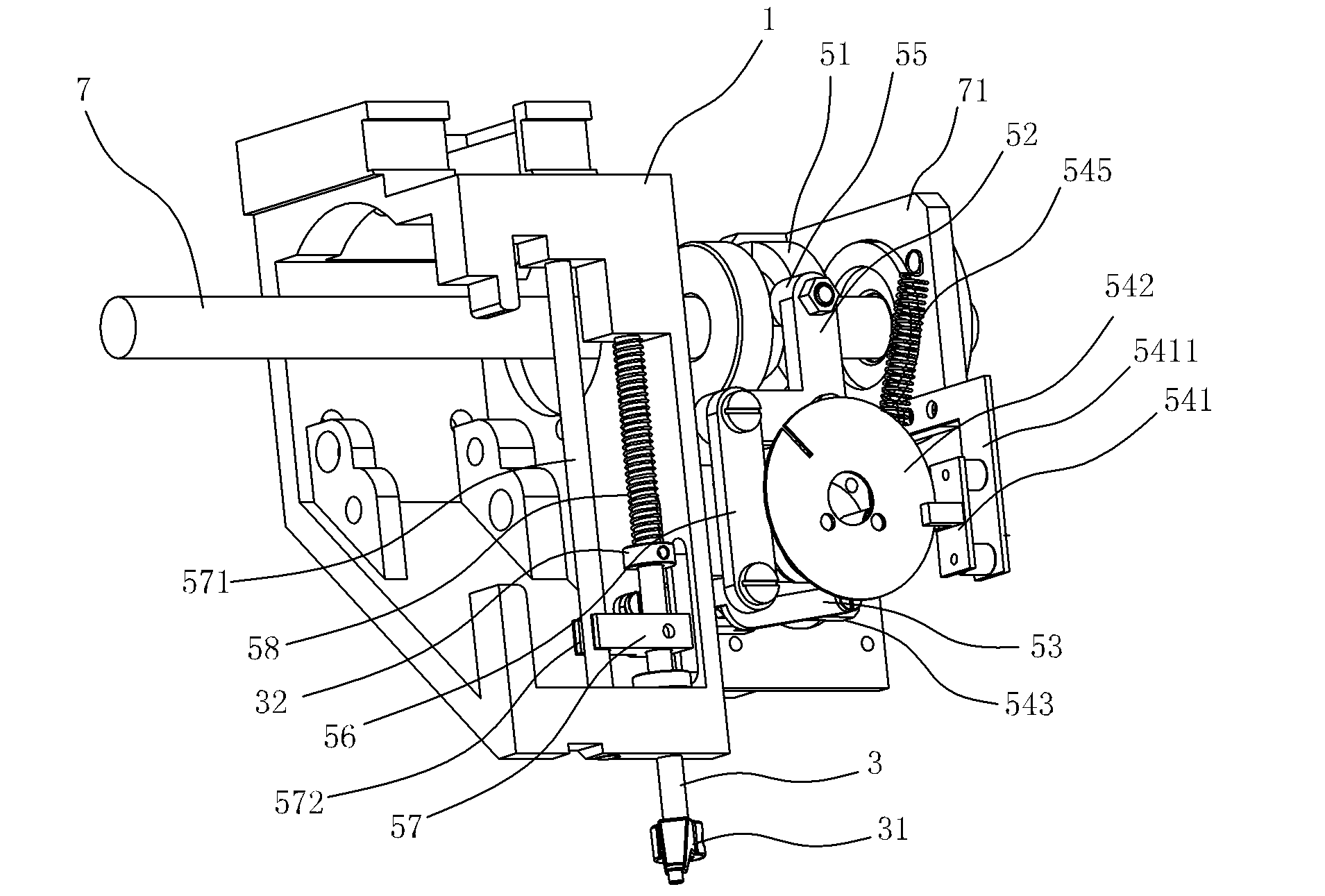
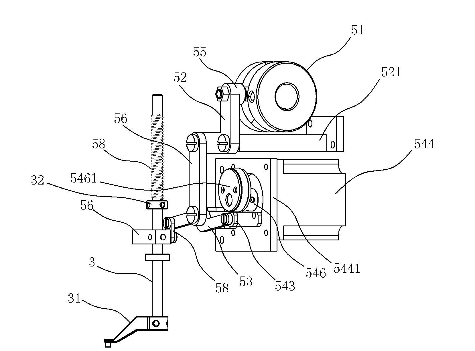
[0018] refer to Figure 1 to Figure 4 Shown, combined with an embroidery machine using an independent presser foot drive system for detailed description:

[0019] An embroidery machine that adopts an independent presser foot drive system includes a frame (not shown in the figure), a machine head 1 arranged on the frame, an upper shaft 7 arranged laterally on the frame 1 through an upper shaft seat 71, which can be horizontally Needle bar box 2 movably arranged on the machine head 1, several needle bars 4 arranged on the needle bar box 2 movable up and down, connected to drive the needle bar box 2 to move laterally to select the color-changing drive for a needle bar 4 to work Mechanism (not shown in the figure), the needle bar driving mechanism (not shown in the figure) that the needle bar 4 that connects the driving selection moves up and down, the presser foot bar 3 that can move up and down arranged on the machine head 1, and the connecting drive The presser foot drive mech...


PUM


Abstract

The invention relates to an independent pressure foot driving system of an embroidering machine, which is arranged on a head of the embroidering machine, comprises an upper shaft and is characterized by further comprising a pressure foot bar and a pressure foot driving mechanism, wherein the pressure foot bar is arranged on the head in a mode of moving up and down; the pressure foot driving mechanism is connected with the pressure foot bar and is used for driving the pressure foot bar to move up and down; and the pressure foot driving mechanism comprises a pressure foot cam arranged on the upper shaft, a driving block fixedly arranged on the pressure foot bar and a transmission assembly which is connected between the pressure foot cam and the driving block and is used for converting the rotation motion of the pressure foot cam into the up-and-down motion of the driving block. According to the invention, by improving the arrangement of the pressure foot bar and independent drive of the pressure foot, the embroidering machine can be used for embroidering a thick material or leather. Compared with the prior art, the independent pressure foot driving system has the advantages of simple structure, low cost and the like.

Description

technical field [0001] The invention relates to the field of embroidery machines, in particular to an embroidery machine independent presser foot drive system. Background technique [0002] Embroidery machines generally include a frame, a machine head arranged on the frame, an upper shaft arranged horizontally on the frame, a needle bar box that can be moved laterally on the machine head, and a needle bar box that can be moved up and down. A number of needle bars, a color-changing drive mechanism connected to drive the needle bar box to move laterally to select a needle bar to work, and a needle bar drive mechanism connected to drive the selected needle bar to move up and down. The traditional embroidery machine presser foot is attached to the needle bar. On the bar, a retaining ring is set on the needle bar, and the presser foot is set on the needle bar so that it can move up and down through the supporting member. The needle bar is sleeved with a presser foot spring betwee...

Claims


Application Information

Patent Timeline
Patent Type & Authority Applications(China)
IPC IPC(8): D05C9/20D05C11/06
Inventor 林辉煌林逢春杨绳刚纪金用林金练黄进伟
Owner FUJIAN YONGXIN NUMERICAL CONTROL TECH
Why Eureka
Try Eureka