I-shaped steel joint structure for underground continuous wall and construction method for I-shaped steel joint structure

A technology of underground diaphragm wall and joint structure, which is applied to underwater structures, infrastructure engineering, artificial islands, etc. The effect of retaining sand, improving the overall impermeability and low cost

Inactive Publication Date: 2012-07-04
中煤江南建设发展集团有限公司
View PDF9 Cites 18 Cited by
  • Summary
  • Abstract
  • Description
  • Claims
  • Application Information

AI Technical Summary

Problems solved by technology

After the underground diaphragm wall is greater than a certain depth, the huge water pressure will cause the water and sand on the outside to be brought into the foundation pit along the joints, which will bring a very large risk to the safety of the foundation pit
In addition, as the main side wall of the permanent structure, joint leakage will bring a lot of inconvenience to the normal use of the building, and there are also certain hidden dangers in the durability of the structure.

Method used


Image

  • I-shaped steel joint structure for underground continuous wall and construction method for I-shaped steel joint structure
  • I-shaped steel joint structure for underground continuous wall and construction method for I-shaped steel joint structure
  • I-shaped steel joint structure for underground continuous wall and construction method for I-shaped steel joint structure

Examples


Embodiment 2

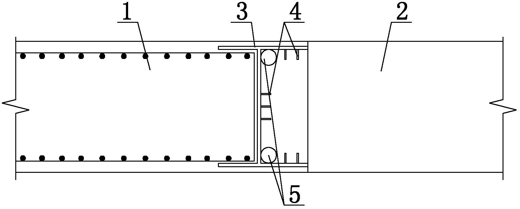
[0027] refer to figure 2 As shown, another underground diaphragm wall I-steel joint structure of the present invention is basically the same as Embodiment 1, the difference is that the inner wall of the I-steel 3 and the rear adjacent wall 2 side is provided with two spray nozzles. The grouting cleaning pipe 5 of the hole is used for cleaning the anchor bar 4 with high-pressure water and grouting with high-pressure grout in the later stage of wall formation, which is convenient for construction and anti-seepage treatment of joints in the later stage of wall formation.

Embodiment 3

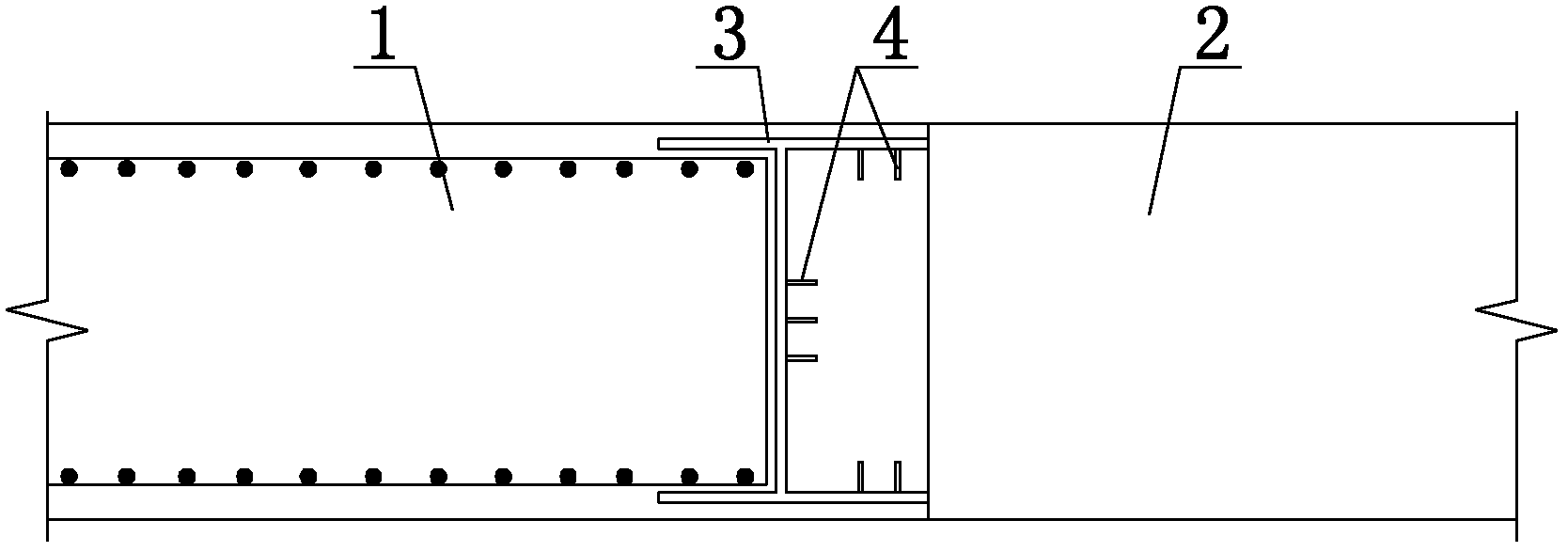
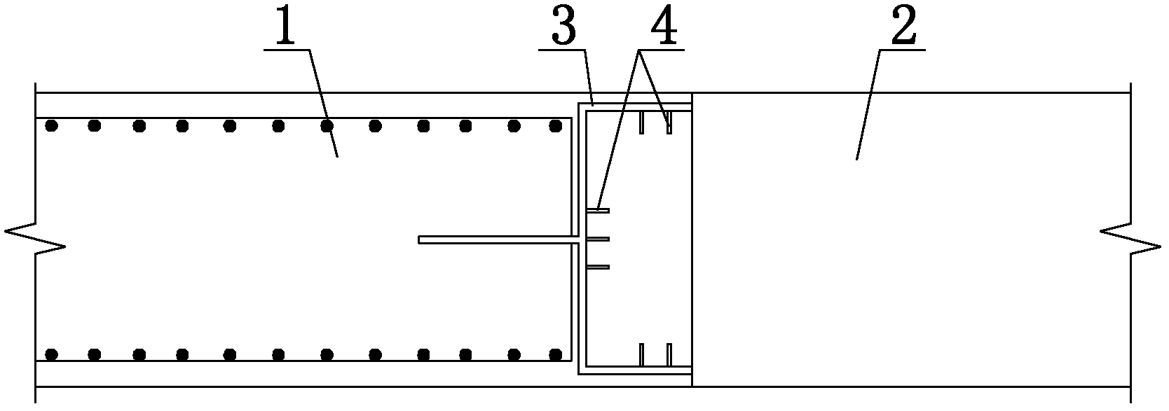
[0029] refer to image 3 As shown, it is another I-beam joint structure of the underground diaphragm wall according to the present invention, which is basically the same as that of Embodiment 1, except that the I-beam 3 connecting the preceding wall panel 1 and the rear adjacent wall panel 2 is a special-shaped joint , its implementation effect is basically the same as in Example 1.

Embodiment 4

[0031] refer to Figure 4 Shown, be one of concrete construction mode of the present invention, specifically comprise the following steps:

[0032] (1) Excavate the ground groove of the preceding wall width 1;

[0033] (2) Make the reinforcement cage of the preceding wall width, and set the I-shaped steel 3 joint at the end of the reinforcement cage of the preceding wall width 1;

[0034] (3) Weld and distribute the anchor bars 4 inside the I-beam 3;

[0035] (4) Hang the reinforcement cage of the leading wall width 1 in the ground groove of the leading wall width 1, and set the mud retaining joint pipe 6 between the outer side of the anchor bar 4 and the inner side of the I-beam 3, and the mud retaining joint pipe 6 is longitudinal Set of three circular tubes;

[0036] (5) Concrete pouring of the preceding wall width 1;

[0037] (6) Excavate the ground groove adjacent to the wall panel 2 on the outside of the joint pipe 6, and make a reinforcement cage adjacent to the wal...


PUM


Abstract

The invention discloses a steel joint structure for an underground continuous wall and a construction method for the steel joint structure, belongs to the technical field of underground continuous walls and aims to provide a steel joint structure for the underground continuous wall which is simple and has a good water stopping effect. According to technical key points, the steel joint structure comprises a front terrae spacing, a rear adjacent terrae spacing and I-shaped steel which is connected between the front terrae spacing and the rear adjacent terrae spacing, wherein anchor bars are distributed among connecting parts between the I-shaped steel and the rear adjacent terrae spacing. The construction method mainly comprises the following steps of: (1) excavating a ground groove of the front terrae spacing; (2) manufacturing a reinforcement cage of the front terrae spacing, and arranging an I-shaped steel joint on the end part of the reinforcement cage of the front terrae spacing; (3) arranging the anchor bars; (4) hoisting and placing the reinforcement cage, and arranging a mud blocking joint pipe on the outer sides of the anchor bars; (5) performing cast molding on concrete; (6) excavating a ground groove of the rear adjacent terrae spacing, manufacturing a reinforcement cage, hoisting a joint pipe, hoisting and placing the reinforcement cage, and cleaning the anchor bars; (7) performing cast molding on the concrete; and (8) circulating the steps from (2) to (7) to form the continuous wall.

Description

technical field [0001] The invention relates to an underground diaphragm wall joint structure, more specifically, to an underground diaphragm wall I-shaped steel joint structure. Background technique [0002] The underground continuous wall is to perform trough-forming operation in advance to form a trough section of a certain length, hang a reinforcement cage in the trough section, pour concrete to form a unit wall section, and then connect the unit wall sections to form a continuous underground reinforced concrete wall. The underground diaphragm wall can be constructed under complex conditions, has a large construction depth, a large bearing capacity of supporting components, and good anti-seepage performance. It is the most reliable support method in foundation pit support. Especially in the sand layer, in order to achieve the water-stop effect, it is necessary to use the underground diaphragm wall, which is the most reliable support method. At present, the underground d...

Claims


Application Information

Patent Timeline
Patent Type & Authority Applications(China)
IPC IPC(8): E02D29/16E02D29/02
Inventor 马文旭莫海鸿孙严
Owner 中煤江南建设发展集团有限公司
Why Eureka
Try Eureka