Municipal drainage system

A technology of municipal drainage system and drainage pump, which is applied in the direction of waterway system, sewage drainage, drainage structures, etc. It can solve the problems of limited drainage capacity, long construction period, and small pressure difference, so as to reduce construction costs, reduce construction and renovation costs Effect

Inactive Publication Date: 2012-07-04
邹杰
View PDF6 Cites 10 Cited by
  • Summary
  • Abstract
  • Description
  • Claims
  • Application Information

AI Technical Summary

Problems solved by technology

Since the drainage pipes often adopt self-flowing drainage with height difference, the pressure difference is small, the flow rate is low, and the drainage capacity is extremely limited, and the reconstruction of one section of the pipeline is only to transform the drainage accumulation point from one place to another, which cannot fundamentally solve the problem
In addition, since the municipal drainage system has been pre-buried below the urban ground, if all the drainage pipes are excavated and reinstalled, the construction period will be long and the cost will be extremely high

Method used


Image

  • Municipal drainage system
  • Municipal drainage system
  • Municipal drainage system

Examples


Embodiment 1

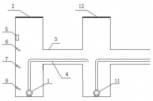
[0015] Municipal drainage system of the present invention, as figure 1 As shown, there are two sets of drainage mechanisms for realizing step-by-step drainage, wherein the first set of drainage mechanisms includes a drainage pump 1 installed in the manhole 2, and the second set of drainage mechanisms includes the next one installed in the manhole 12 of the next level. Level drainage pump 11, drainage pump 1 discharges the water leaked into the manhole 2 on the ground to the next level manhole 12 through the drain pipe 4, and the next level drainage pump 11 discharges the accumulated water in the manhole 12 of the next level into the discharge purpose land 9.

[0016] In this embodiment, an automatic control and detection device 5 is also installed in the above-mentioned manhole 2, and the automatic control and detection device 5 includes a high water level detection probe 6 and an intermediate water level probe respectively installed in the upper part, the middle part and the ...

Embodiment 2

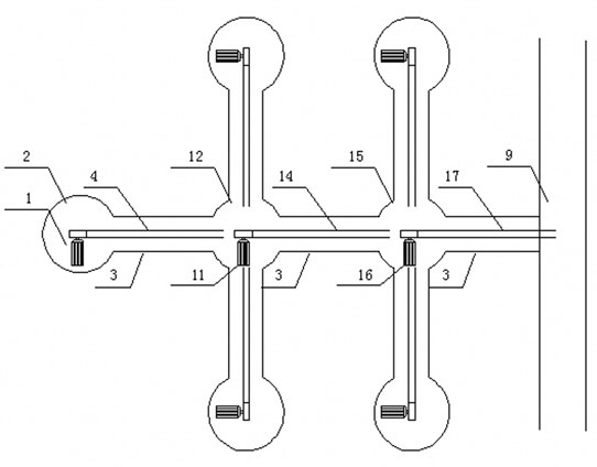
[0025] Municipal drainage system of the present invention, as figure 2 As shown, there are three sets of drainage mechanisms for realizing step-by-step drainage, wherein the first set of drainage mechanisms includes a drainage pump 1 installed in the manhole 2, and the second set of drainage mechanisms includes a next-level drainage mechanism installed in the next-level manhole 12. Drainage pump 11, the third set of drainage mechanism includes the next level of drainage pump 16 installed in the next level of manhole 15, and drainage pump 1 drains the water leaking into the manhole 2 on the ground to the next level through drainpipe 4 level manhole 12, the next level drainage pump 11 will drain the accumulated water in the next level manhole 12 to the next level manhole 15 through the drainage pipe 14, and then the next level drainage pump 16 will pass the drainage pipe 17 to the next level manhole The stagnant water in 15 is discharged into discharge destination 9. Equally, ...


PUM


Abstract

The invention relates to a municipal drainage system, which comprises at least two drainage mechanisms implementing stepwise drainage. One drainage mechanism comprises a drain pump (1) mounted in a manhole (2). The second drainage mechanism comprises a next-level drain pump (11) mounted in a next-level manhole (12). The drain pump (1) discharges water leaking into the manhole (2) from the surface through a drain pipe (4) to the next-level manhole (12), and the next-level drain pump (11) discharges accumulated water inside the next-level manhole (12) to a discharge destination (9). Based on the existing actual condition, an existing drainage system is substantially unchanged, and only the drain pump (1), the drain pipe (4) and a control device (5) are mounted in the existing drainage system. The municipal drainage system is automatically used under special conditions, discharge of accumulated water is accelerated, and urban waterlogging can be avoided. The municipal drainage system is simple, feasible, reliable in control, low in operation cost and effective in drainage and meets environmental requirements.

Description

technical field [0001] The invention relates to a municipal drainage system, in particular to a municipal drainage system used in large and medium-sized cities with poor drainage, and belongs to a modification technology of the municipal drainage system. Background technique [0002] Due to design changes and changes in use functions of the municipal drainage system, some pipelines in the drainage system are not smooth enough, and the generally designed flow rate is too small. When the rainfall is heavy or rapid, the drainage is insufficient, causing urban waterlogging and serious water accumulation; or due to water supply pipes Damaged roads and a large amount of water leakage will also cause water accumulation in the city. The above phenomena often appear in large and medium-sized cities, seriously affecting traffic travel and life. Since the drainage pipes often adopt self-flowing drainage with height difference, the pressure difference is small, the flow rate is low, an...

Claims


Application Information

Patent Timeline
Patent Type & Authority Applications(China)
IPC IPC(8): E03F1/00E03F5/22
Inventor 邹杰
Owner 邹杰
Why Eureka
Try Eureka