Compensation gear pump for annular spoke springs

A technology of spring compensation and gear pump, which is applied in the direction of pumps, pump components, rotary piston pumps, etc., can solve the problems of no effective compensation methods and measures, end face wear can not be effectively compensated, etc., to achieve market application potential Huge, easy to manufacture, innovative effects

Inactive Publication Date: 2012-07-04
HUNAN BALING FURNACE ENERGY CONSERVATION
View PDF13 Cites 5 Cited by
  • Summary
  • Abstract
  • Description
  • Claims
  • Application Information

AI Technical Summary

Problems solved by technology

The problem that has not been effectively solved is that after long-term high-speed operation, the inevitable wear of the end face cannot be effectively compensated.
my country patent authorization announcement number: CN1059019C swing vane pump; my country patent authorization announcement number: CN100374725C rotary vane pump; The internal gear pump of plastic casing; my country's patent authorization announcement number: CN101120175B and my country's patent authorization announcement number: CN101403382B a kind of gear pump for micro-miniature turbojet engine etc., all do not see the method and the measure that have practical and effective compensation, solve Gap Control Problems of End Surface Wear of Rotary Positive Displacement Pumps

Method used


Image

  • Compensation gear pump for annular spoke springs
  • Compensation gear pump for annular spoke springs
  • Compensation gear pump for annular spoke springs

Examples


Embodiment Construction

[0017] The structure and working principle of the present invention will be further described in detail with reference to the drawings and embodiments.

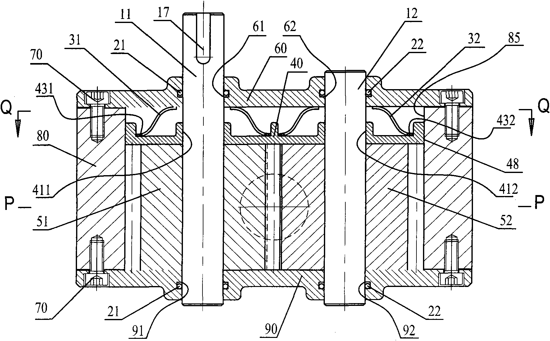
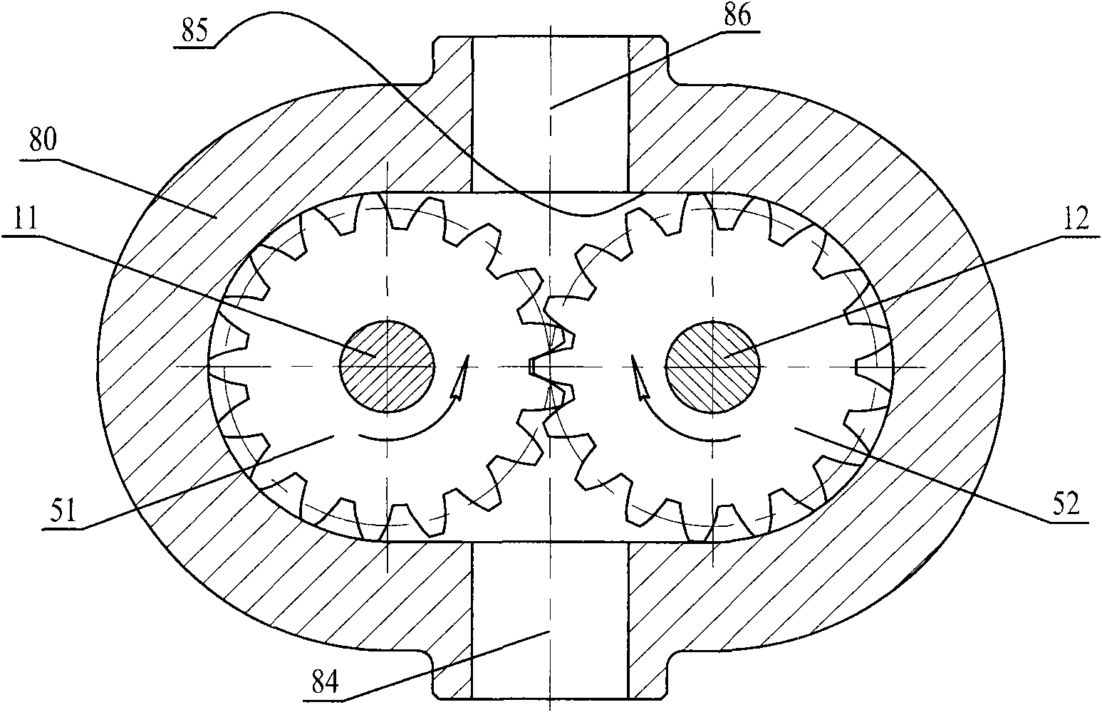
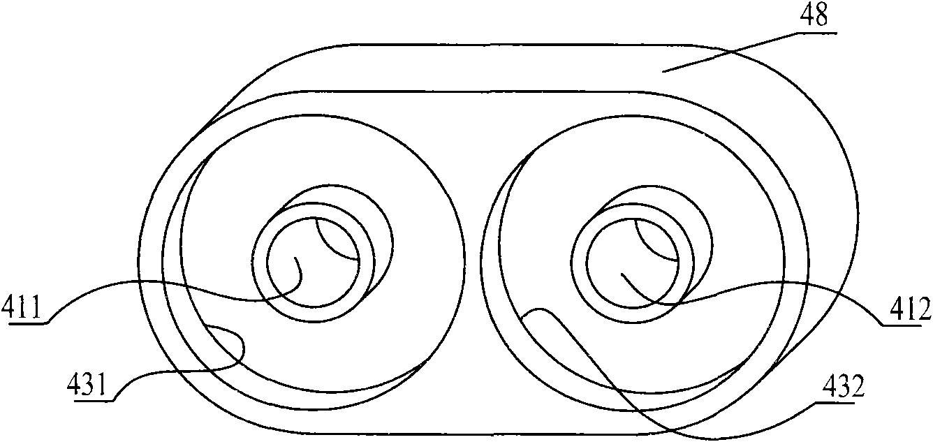
[0018] A ring spoke spring compensation gear pump, comprising a driving shaft 11, a driven shaft 12, a master gear 51, a slave gear 52, a ring spoke main spring 31, a ring spoke slave spring 32, an end surface compensation disc 40, a front outer end cover 60, End cover screw 70, pump body 80, rear outer end cover 90, the two ends of the pump body 80 are perpendicular to the double semicircular holes 85, and the front outer end cover 60 and the rear outer end cover 90 are respectively covered on the two ends. There are end cover screws 70 to fasten; the front cover driving shaft hole 61 of the front outer end cover 60 and the rear cover driving shaft hole 91 of the rear outer end cover 90 are on the same axis; the front outer end cover 60 of the The front cover driven shaft hole 62 and the rear cover driven shaft hole 92 of th...


PUM


Abstract

A compensation gear pump for annular spoke springs comprises a drive shaft, a driven shaft, a main gear, a slave gear, an annular spoke main spring, an annular spoke slave spring, an end surface compensation plate, a front outer end cover, an end cover bolt, a pump body and a rear outer end cover, wherein the end surface compensation plate is arranged between the main gear and the front outer end cover as well as between the slave gear and the front outer end cover; the circular ring of the annular spoke main spring is fixed at the concave main annular corner on the back of the compensation plate; the spoke of the annular spoke main spring is propped against the inner side surface of the front outer end cover; the circular ring of the annular spoke slave spring is fixed at the concave slave annular corner on the back of the compensation plate; and the spoke of the annular spoke slave spring is propped against the inner side surface of the front outer end cover. According to the axial rebounding force generated because the spokes of the annular spoke main spring and the annular spoke slave spring are respectively propped against the inner side surface of the front outer end cover, the front plane surface of the end surface compensation plate is clung to the end plane surfaces on one side of the main gear and one side of the slave gear, so that the end plane surfaces on the other sides of the main gear and the slave gear are clung to the inner plane surface of the rear outer end cover to ensure the efficient operation of the gear pump all the while.

Description

technical field [0001] The invention belongs to the field of mechanical engineering. The international patent classification is F04D non-variable displacement pump, which relates to an energy conversion rotary positive displacement pump which converts mechanical energy into liquid pressure energy, in particular to a ring spoke spring compensation gear pump. Background technique [0002] Rotary positive displacement pumps have the advantage of high efficiency, but their efficiency is significantly reduced after long-term wear and tear. The main reason for the above defects is that the end face movable isolation between the high-pressure chamber and the low-pressure chamber cannot effectively seal. If the tolerance size of the end face is too small, it is easy to be stuck due to thermal expansion. If the tolerance size of the end face is too large, it will not be effective in sealing, and the sealing effect will be worse after long-term operation and wear. The production line h...

Claims


Application Information

Patent Timeline
Patent Type & Authority Applications(China)
IPC IPC(8): F04C2/18F04C15/00
Inventor 张意立
Owner HUNAN BALING FURNACE ENERGY CONSERVATION
Why Eureka
Try Eureka