Sliding vane pump and method using sliding vane pump to convey fluid

A technology for transporting fluid and sliding vane pumps, which is applied in the hydraulic field, can solve the problems of difficulty in adapting to tubular spaces, large radial dimensions of sliding vane pumps, and small pumping pressure of sliding vane pumps, and achieve a reduction in radial dimensions and radial volume, high lift capacity, effect of potential energy

Active Publication Date: 2012-07-04
PETROCHINA CO LTD
View PDF5 Cites 7 Cited by
  • Summary
  • Abstract
  • Description
  • Claims
  • Application Information

AI Technical Summary

Problems solved by technology

[0007] The invention provides a sliding vane pump and a method for transporting fluid by using the sliding vane pump to solve the problems that the existing sliding vane pump has a large radial dimension, a large volume of the sliding vane pump, and it is difficult to adapt to a narrow tubular space
In addition, the present invention can also solve the problem that the pumping pressure of the sliding vane pump is small

Method used


Image

  • Sliding vane pump and method using sliding vane pump to convey fluid
  • Sliding vane pump and method using sliding vane pump to convey fluid
  • Sliding vane pump and method using sliding vane pump to convey fluid

Examples


Embodiment Construction

[0052] In order to have a clearer understanding of the technical features, objects and effects of the present invention, the specific embodiments of the present invention will now be described with reference to the accompanying drawings.

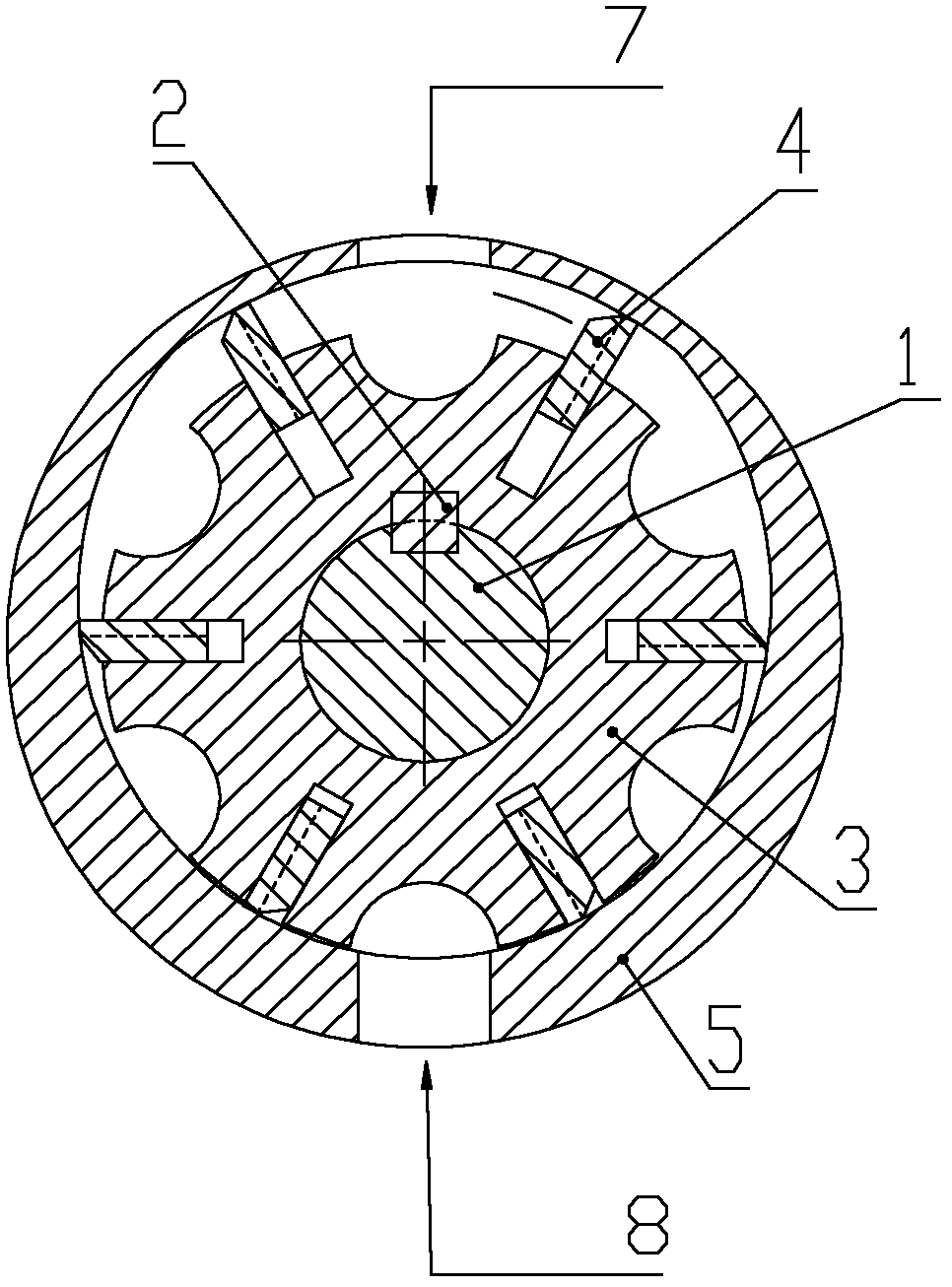
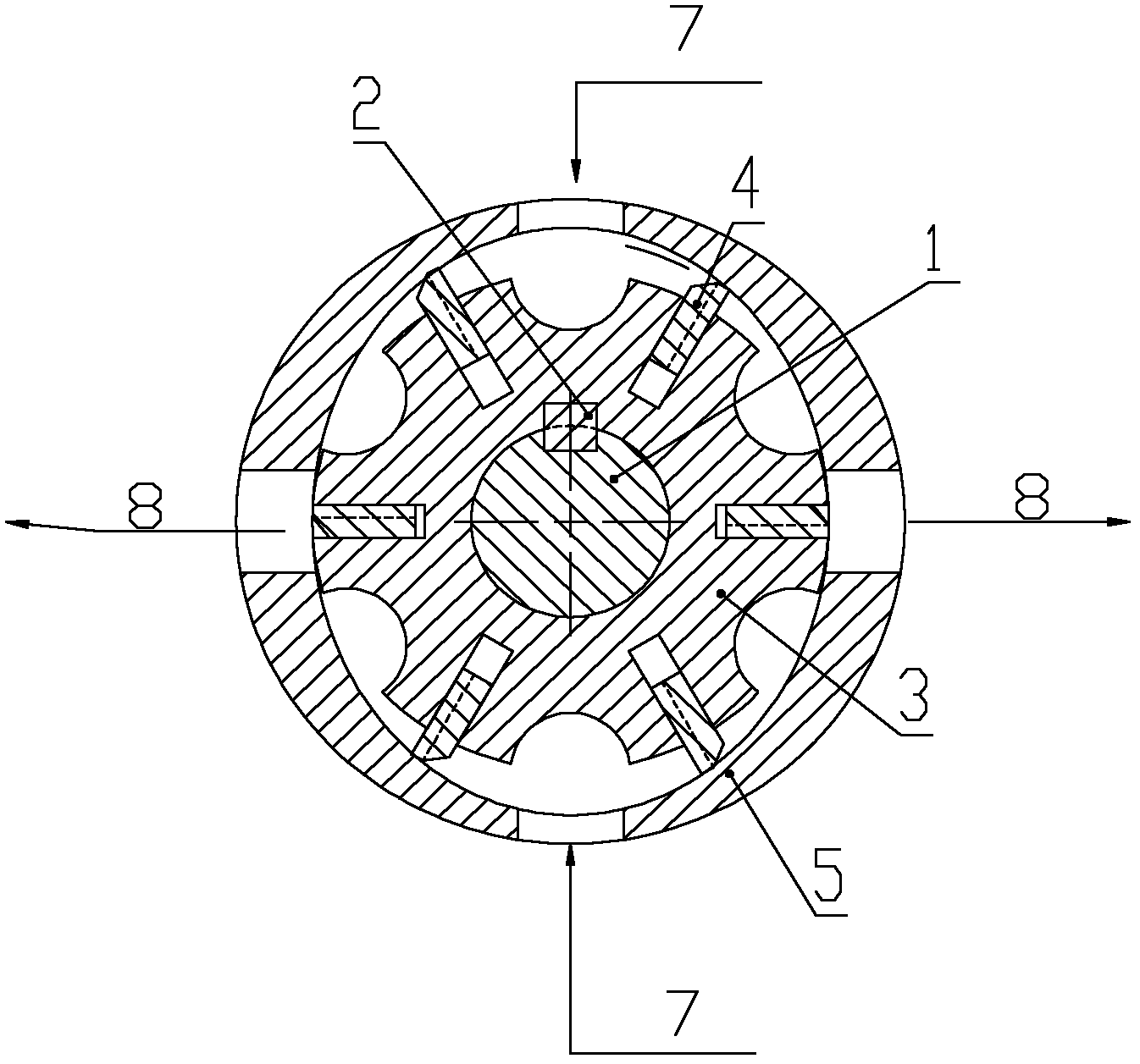
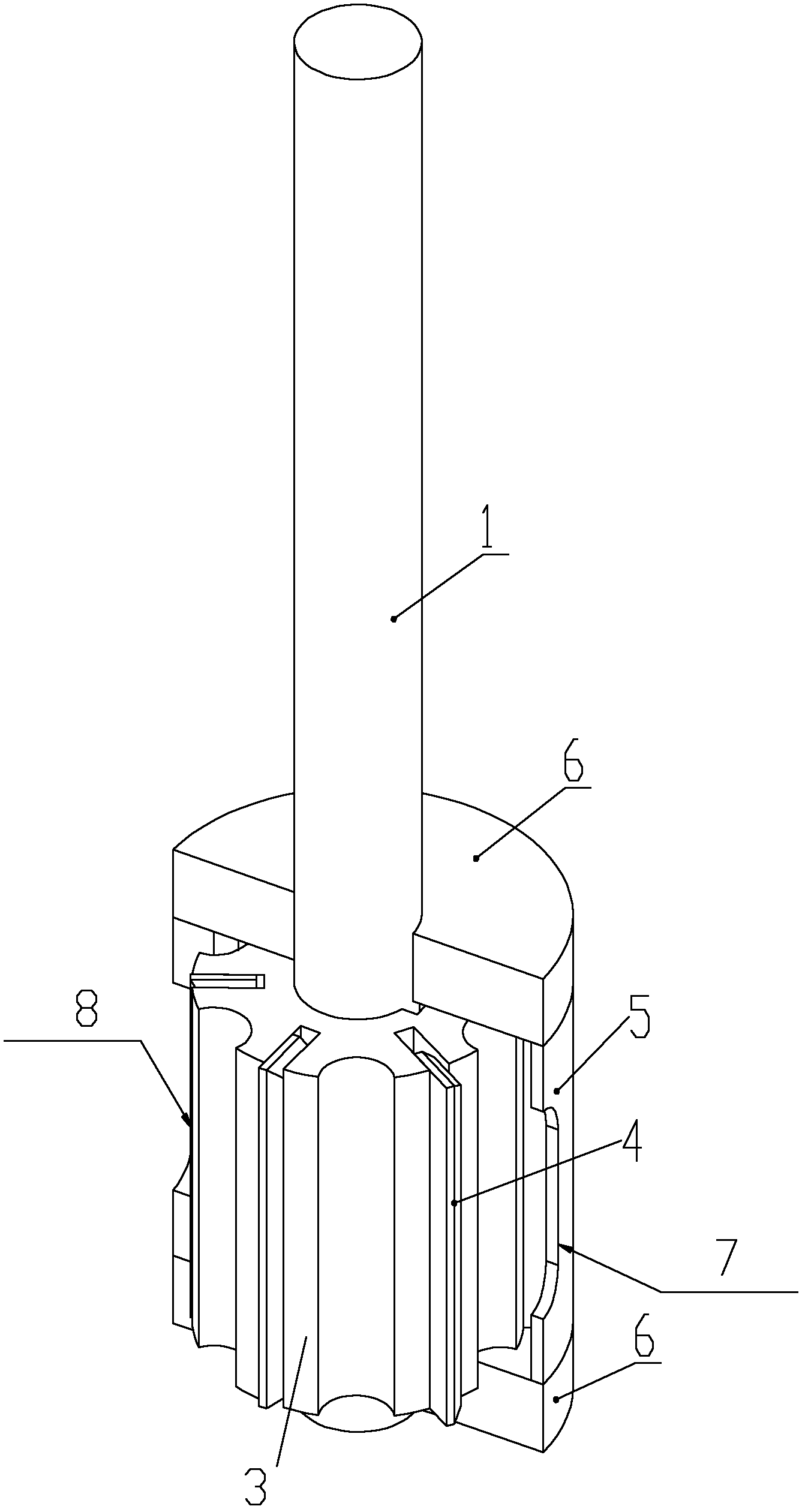
[0053] like Figure 4 to Figure 6 As shown, the present invention proposes a sliding vane pump, the sliding vane pump has a cylindrical pump casing 5, and the pump casing 5 is provided with: a drive shaft 1, a rotor 3 sleeved on the drive shaft, the rotor 3. The sliding vane 4 is fixedly connected with the drive shaft 1 through the connecting key 2 and is arranged on the rotor 3. The sliding vane 4 is in contact with the inner cavity of the pump casing 5, and the end of the pump casing 5 is provided with There is an end cover, and the sliding vane pump also has a sliding vane pump suction port 70 and a sliding vane pump discharge port 80, and the sliding vane pump suction port 70 and / or the sliding vane pump discharge port 80 are located on ...


PUM


Abstract

The invention provides a sliding vane pump and a method using the sliding vane pump to convey fluid. The sliding vane pump is provided with a cylindrical pump casing, and the pump casing is internally provided with a driving shaft, a rotor sleeved on the driving shaft, and a sliding vane arranged on the rotor, wherein the sliding vane and an inner cavity of the pump casing are sealed in a contact manner; an end cover is arranged at the end part of the pump casing; the sliding vane pump further has a sliding vane pump suction port and a sliding vane pump discharge port; and the sliding vane pump suction port and / or the sliding vane pump discharge port are located on the end cover of the pump casing. The invention further provides a sliding vane pump, and the sliding vane pump includes a plurality of cylindrical pump casing, and has a sliding vane pump suction port and a sliding vane pump discharge port; the sliding vane pump suction port and / or the sliding vane pump discharge port are respectively located on the end cover; and fluid transfer openings penetrating the upper end surfaces and the lower end surfaces of partitions are arranged on the partitions. According to the method using the sliding vane pump, the fluid is sucked and / or discharged in the direction of the end part of the pump casing so as to pump.

Description

technical field [0001] The invention relates to the hydraulic field, in particular to a sliding vane pump and a method for transporting fluid by using the sliding vane pump. Background technique [0002] Sliding vane pump is a commonly used positive displacement pump, which is widely used in the industrial field of gathering, transportation and lifting. It has strong self-priming ability, and is especially suitable for unloading oil at the wharf of oil tankers, cargo oil on board, stripping tanks, and unloading tanks by trains. And other occasions, as well as oil tank trucks, fuel trucks, oil depots, and gas stations for oil delivery. Sliding vane pumps can be used to transfer light oils, and viscous oils are better. The working principle of ordinary single-acting sliding vane pump is as follows: figure 1 shown. Generally, the single-acting sliding vane pump is mainly composed of the following parts: drive shaft 1, connecting key 2, rotor 3, vane 4, also called blade, and...

Claims


Application Information

Patent Timeline
Patent Type & Authority Applications(China)
IPC IPC(8): F04C2/344F04C15/06
CPCF04C2240/70F04C2/3446F04C2/3442F04C11/001F04C15/06
Inventor 张立新郝忠献沈泽俊裴晓含李益良王全斌王同斌
Owner PETROCHINA CO LTD
Why Eureka
Try Eureka