

Throttle loop
A circuit and oil return port technology, applied in the hydraulic field, can solve problems such as too sensitive adjustment and unfavorable system stability
- Summary
- Abstract
- Description
- Claims
- Application Information
AI Technical Summary
Problems solved by technology
Method used
Image


Examples
Embodiment Construction
[0051] Specific embodiments of the present invention will be described in detail below in conjunction with the accompanying drawings. It should be understood that the specific embodiments described here are only used to illustrate and explain the present invention, and are not intended to limit the present invention.
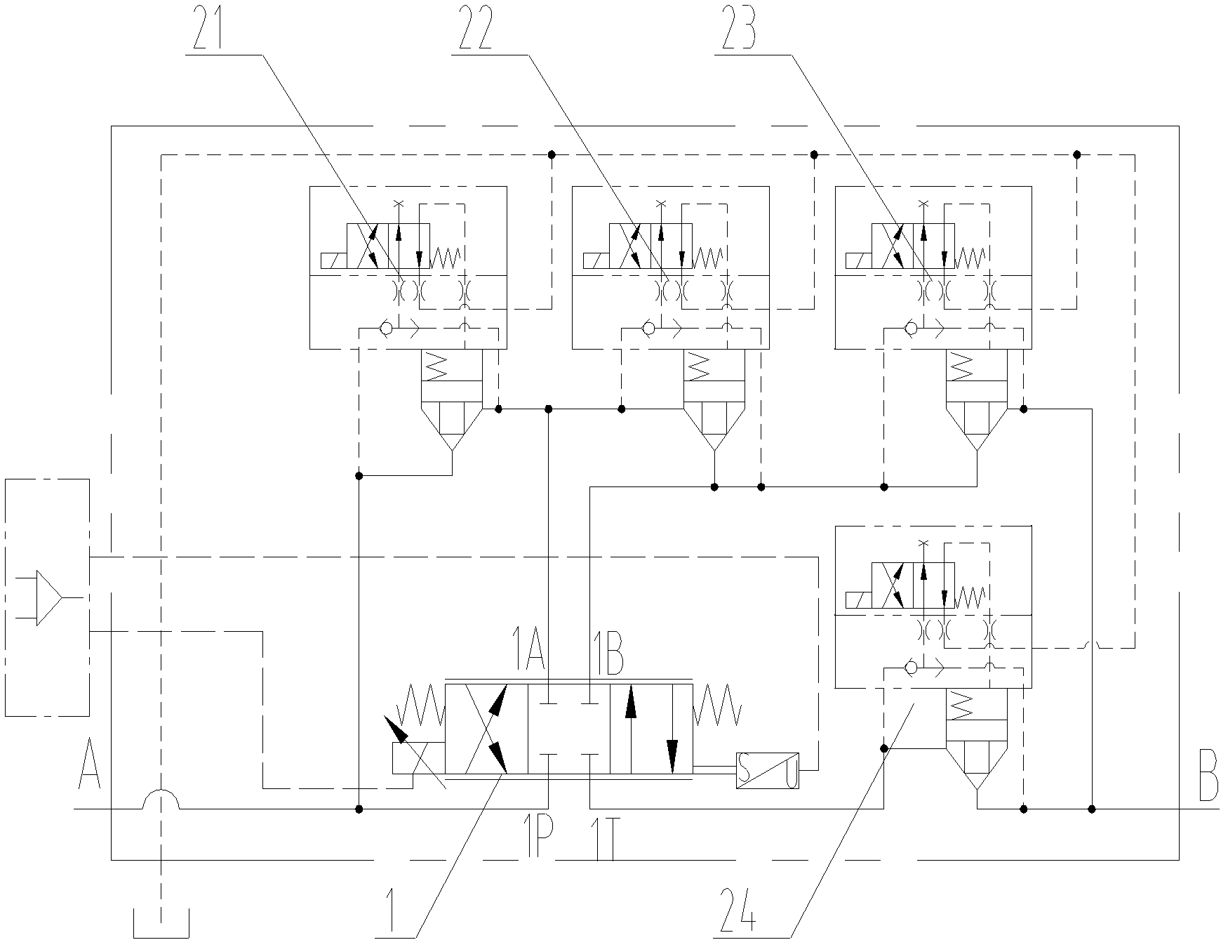
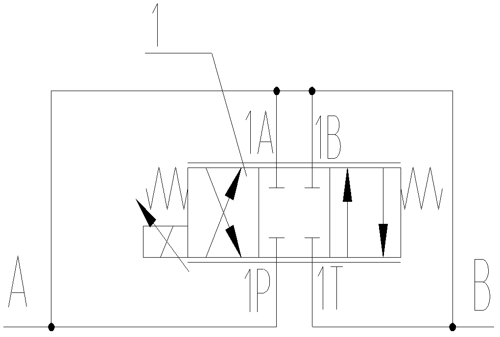
[0052] Such as figure 1 As shown, a throttling circuit is provided according to an embodiment of the present invention, wherein the throttling circuit includes a first working port A, a second working port B, a directional flow control valve 1 and four on-off valves 21, 22, 23, 24, the first working port A communicates with the pressure oil port 1P of the directional flow control valve 1, and the four on-off valves 21, 22, 23, 24 are connected in series between the first working port A and the directional flow control valve 1 respectively. Between the first working oil port 1A of the flow control valve 1, between the first working oil port 1A and the second wor...
PUM
 Abstract
Description
Claims
Application Information