Electric gate valve

A plug-in valve, electric technology, applied in sliding valves, valve details, valve devices and other directions, can solve the problems of polluted materials, large friction resistance, heavy weight, etc., to achieve low energy consumption, low friction resistance, high load-bearing performance. Effect

Active Publication Date: 2014-05-28
XIAMEN MEIGANQIDONG MATERIAL CONVEYING ENG
View PDF9 Cites 0 Cited by
  • Summary
  • Abstract
  • Description
  • Claims
  • Application Information

AI Technical Summary

Problems solved by technology

[0007] First, since the bottom of the valve plate is not equipped with a self-cleaning mechanism, the material entering the valve body cannot be brought out with the closing of the valve plate, which will cause the accumulation of materials inside the valve body and even hinder the movement of the valve plate
[0008] Second, since the two ends of the slide rail are open, fine materials are easy to fall into the slide rail, increasing the frictional resistance between the valve plate and the slide rail;
[0009] 3. Since the valve plate is made of cast steel plate or cast iron, and the slide rails are made of metal slide rails, the frictional resistance of the valve plate is large when it moves, increasing the load on the motor, but the use of lubricants will pollute the material;
[0010] Four, because the valve body is made of thick cast steel plate or cast iron, its weight is heavy;
[0011] Fifth, since the upper end cover is not provided with an observation hole, and the material of the upper end cover is also non-transparent, it is impossible to observe and debug the moving parts of the plug-in valve

Method used


Image

  • Electric gate valve
  • Electric gate valve
  • Electric gate valve

Examples


Embodiment Construction

[0048] The present invention will be described in detail below in conjunction with the accompanying drawings and specific embodiments.

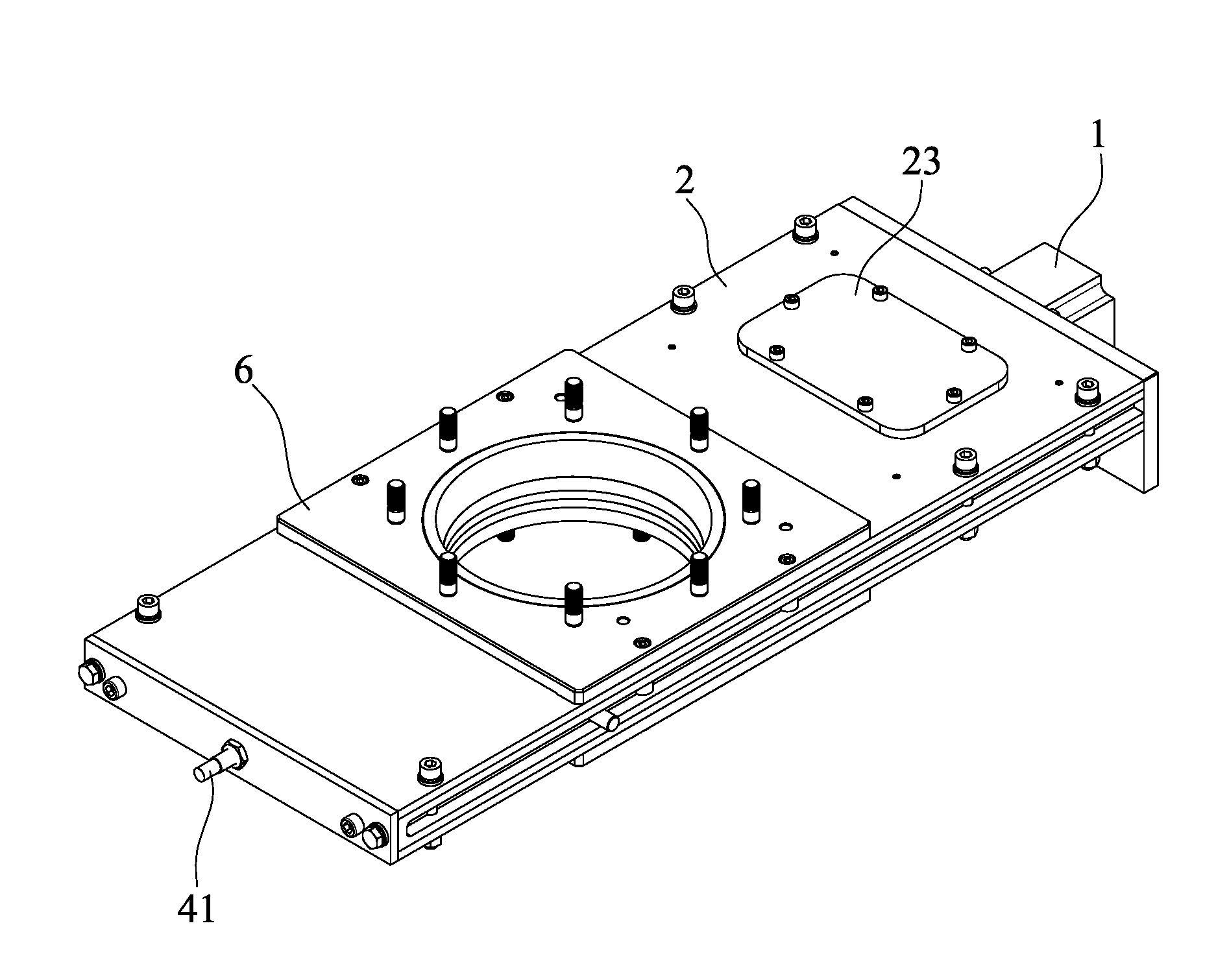
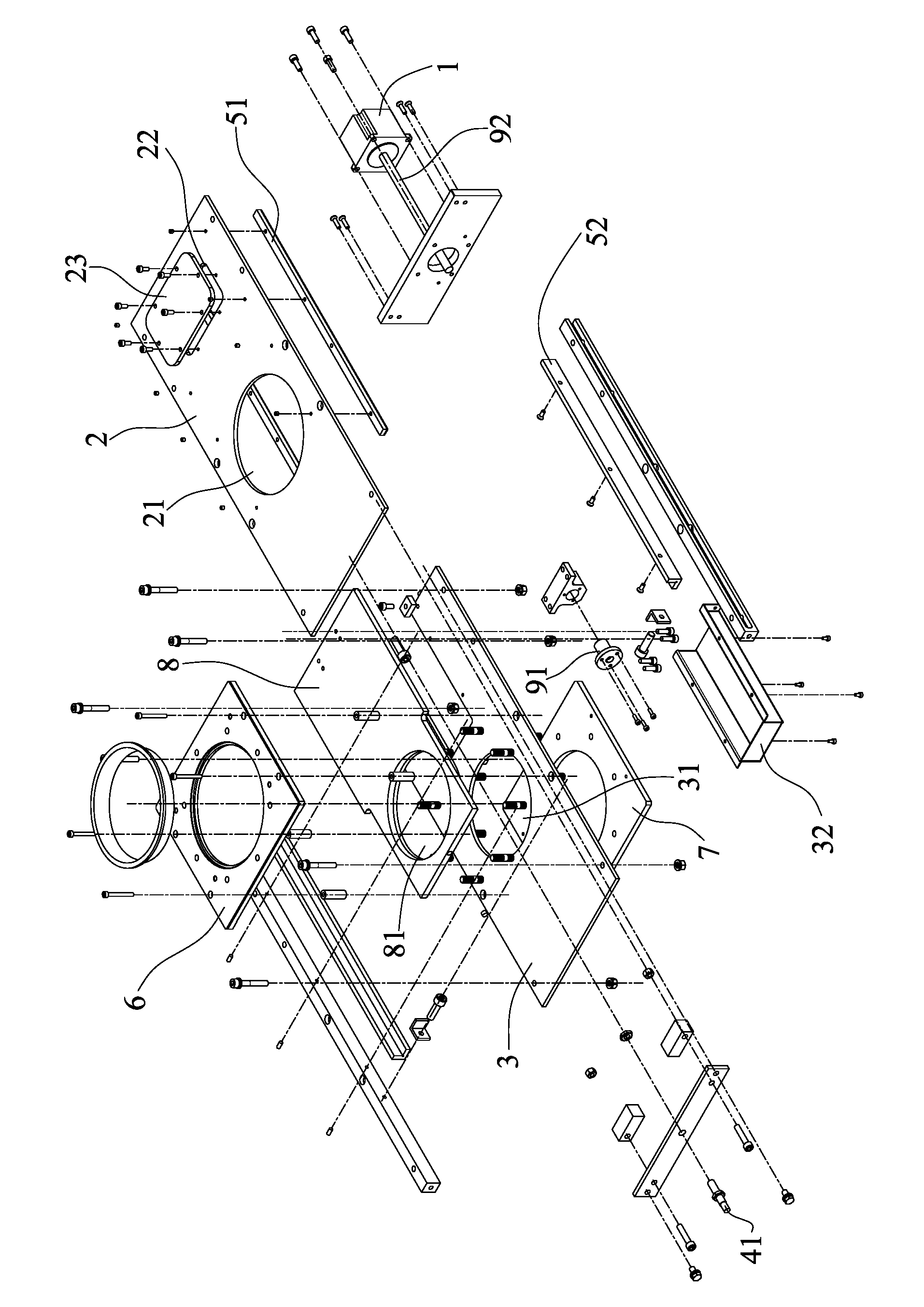
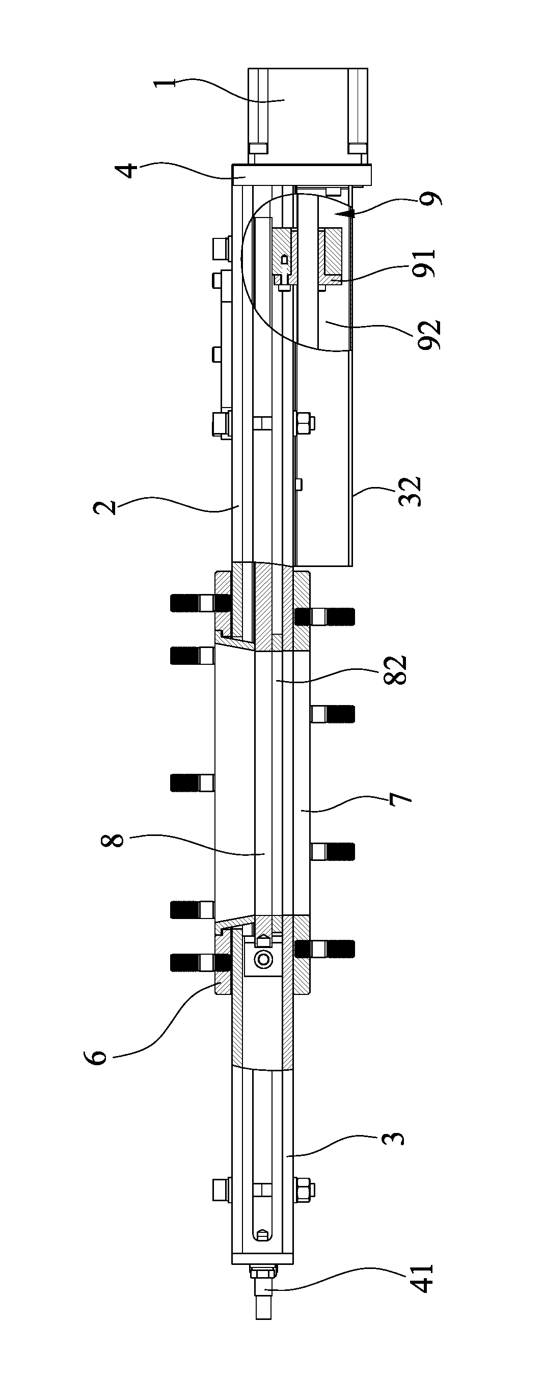
[0049] refer to Figure 1 to Figure 4 As shown, an electric gate valve disclosed by the present invention includes a motor 1 , an upper end cover 2 , a lower end cover 3 , a valve body frame 4 , a slide rail 5 , an inlet flange 6 , an outlet flange 7 and a valve plate 8 .

[0050] The upper end cover 2 is installed on the valve body frame 4, and the upper end cover 2 has a material inlet 21, and the inlet flange 6 is installed on the upper end cover 2 material inlet 21; the valve body frame 4 can be composed of the front valve body frame, the rear The valve body frame, the left valve body frame and the right valve body frame are assembled, and this structure can better ensure the airtightness of the present invention; it can also be integrally formed.

[0051] The lower end cover 3 is installed on the valve body frame 4 , the lower end cover...


PUM


Abstract

The invention discloses an electric gate valve, which comprises a motor, an upper end cap, a lower end cap, a valve frame, two sliding rails, an inlet flange, an outlet flange and a valve plate. The upper end cap is mounted on the valve frame and provided with a feed port, the inlet flange is mounted on the feed port of the upper end cap, the lower end cap is mounted on the valve frame and provided with a discharge port, the outlet flange is mounted below the discharge port of the lower end cap, the two mutually parallel sliding rails are arranged between the upper end cap and the lower end cap and mounted on the valve frame and the upper end cap, the motor is mounted on the valve frame, a circular opening is arranged on the valve plate, the valve plate is connected with the motor through a transmission mechanism and moves between the two sliding rails, and a self-cleaning ring is arranged at the bottom of the opening of the valve plate and attached to the lower end cap. The electric gate valve has a self-cleaning function and is high in bearing performance, low in friction resistance, light in weight and fine in air tightness.

Description

technical field [0001] The invention relates to a material flow control device, in particular to an electric gate valve. Background technique [0002] In the prior art, the electric plug-in valve generally includes a motor, an upper end cover, a lower end cover, a valve body frame, a slide rail, an inlet flange, an outlet flange and a valve plate; the inlet flange is installed on the upper end cover, and the upper end cover is installed on the On the valve body frame, the upper end cover is provided with a feed port; the outlet flange is installed under the lower end cover, the lower end cover is installed on the valve body frame, and the lower end cover is provided with a discharge port corresponding to the feed port; the connection between the upper end cover and the lower end cover Two parallel slide rails are arranged between them, and the slide rails are installed on the valve body frame; the valve plate is slidably supported on the slide rails, and an opening correspon...

Claims


Application Information

Patent Timeline
Patent Type & Authority Patents(China)
IPC IPC(8): F16K3/04F16K31/04F16K3/316F16K31/50
Inventor 苏骑徐正松蒋力董高洋
Owner XIAMEN MEIGANQIDONG MATERIAL CONVEYING ENG
Why Eureka
Try Eureka