Energy dissipating water distributor of cross flow type cooling tower with hydrodynamic fan

A technology of hydrodynamic fans and cooling towers, applied in the field of cooling towers, can solve problems such as uneven water flow and environmental pollution, and achieve the effects of eliminating water splashes, avoiding splashes, and good anti-corrosion effects

Inactive Publication Date: 2013-04-10
NANJING XINGFEI COOLING EQUIP
View PDF6 Cites 1 Cited by
  • Summary
  • Abstract
  • Description
  • Claims
  • Application Information

AI Technical Summary

Problems solved by technology

[0004] The purpose of the present invention is to design a non-splashing, low-noise, water-distributing cooling tower that solves the problems of uneven water flow and environmental pollution caused by noise and splashing due to the absence of a suitable energy-dissipating water separator in the existing cross-flow cooling tower. More uniform environment-friendly cross-flow hydraulic fan cooling tower energy dissipation water separator

Method used


Image

  • Energy dissipating water distributor of cross flow type cooling tower with hydrodynamic fan
  • Energy dissipating water distributor of cross flow type cooling tower with hydrodynamic fan
  • Energy dissipating water distributor of cross flow type cooling tower with hydrodynamic fan

Examples


Embodiment Construction

[0019] The present invention will be further described below in conjunction with the accompanying drawings and embodiments.

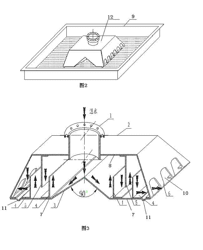
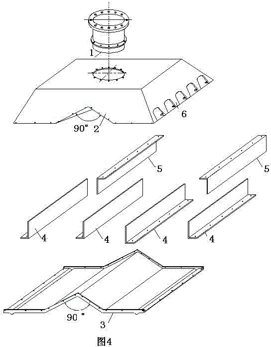
[0020] Such as image 3 , 4 shown.

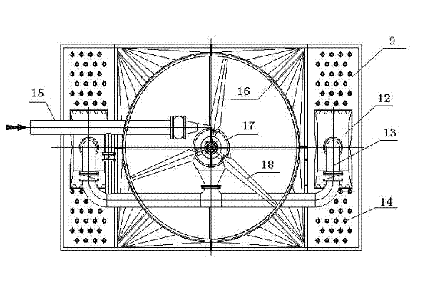
[0021] An energy dissipating water separator for a cooling tower of a cross-flow hydraulic fan can be entirely formed by pressing glass fiber reinforced plastics, and it is installed in the water distribution tank 9 of the cooling tower, such as figure 1 , 2 shown. The whole of the energy dissipating water separator is a quadrilateral frustum of cone structure, including the shell box 2, and the upper part of the shell box 2 is provided with a water inlet interface 1, which is characterized in that the bottom of the shell box 2 and the relative position of the water inlet interface 1 are provided. There is an inverted V-shaped central decompression splitter plate 3, the angle of the inverted V can be between 70-110 degrees, preferably 90 degrees, such as image 3 As shown, on the bottom plate 7 on both sides...


PUM


Abstract

An energy dissipating water distributor of a cross flow type cooling tower with a hydrodynamic fan comprises a housing box (2). A water inlet connector (1) is arranged on the upper portion of the housing box (2). The energy dissipating water distributor is characterized in that an inverted-V-shaped central pressure reducing splitter plate (3) is arranged at the bottom of the housing box (2) and is positioned opposite to the water inlet connector (1), a plurality of lower energy dissipating plates (4) are mounted on a bottom plate (7) at intervals, a plurality of upper energy dissipating plates (5) are mounted on an upper plate (8) opposite to the bottom plate, the lower end of each upper energy dissipating plate (5) is positioned between the two correspondingly adjacent lower energy dissipating plates (4), gaps are arranged between the upper end of each lower energy dissipating plate (4) and the upper plate (8) and between each upper energy dissipating plate (5) and the bottom plate (7), water flows through the gaps, a plurality of water distributing notches (10) are disposed on two side splitter plates (6) of the housing box (2), and water flows into water distributing grooves (9) via the water distributing notches (10) according to water flow, and forms fan-shaped diffusion flow by the aid of the water distributing notches (10). The energy dissipating water distributor is simple in structure and convenient in installation. The problem of splashing of water fed into the tower is solved, noise is reduced, water distribution uniformity is improved, and a cooling performanceis enhanced to the greatest extent.

Description

technical field [0001] The invention relates to a cooling tower, in particular to an energy-dissipating water separator of a cross-flow cooling tower driven by a water turbine to rotate a fan, in particular to an energy-dissipating water separator of a cross-flow hydraulic fan cooling tower. Background technique [0002] At present, in the design of the water separator of the ordinary cross-flow steel structure tower, a box with small slits around it is generally used to cover the water tray, and the incoming water flows directly into the box, and then flows into the shower through the small slits. In the sink. This method will cause the following problems: there is no energy dissipation device at the water inlet, and when the water enters the water separator, it will make a lot of noise when it hits the tank; The small strip mouth directly hits the periphery of the shower tank to cause water to overflow the tank and overflow. And because the flow rate of water distributio...

Claims


Application Information

Patent Timeline
Patent Type & Authority Patents(China)
IPC IPC(8): F28F25/02
Inventor 顾星康
Owner NANJING XINGFEI COOLING EQUIP
Why Eureka
Try Eureka