Vibration reduction and impact resistance method for spaceflight sensor

A technology of sensor and root mean square value, which is applied in the direction of the moving element of the damping part of the measuring device, can solve the problems of secondary collision, affecting stability requirements, affecting product performance, etc., and achieves the effect of stable performance

Active Publication Date: 2012-07-04
BEIJING RES INST OF TELEMETRY +1
View PDF2 Cites 5 Cited by
  • Summary
  • Abstract
  • Description
  • Claims
  • Application Information

AI Technical Summary

Problems solved by technology

[0003] The existing design methods of vibration reduction and shock resistance for aerospace sensors do not have a deep understanding of vibration and shock, and cannot solve the essence of the problem when reflected in the specific design. If you don't have a deep understanding, some vibration and shock resistance designs do not bring any benefits to the product, and even affect the performance of the product
There are also opinions that vibration reduction and shock resistance cannot be taken into account. They believe that as long as the excitation frequency is more than 1.414 times the natural freque

Method used


Image

  • Vibration reduction and impact resistance method for spaceflight sensor
  • Vibration reduction and impact resistance method for spaceflight sensor
  • Vibration reduction and impact resistance method for spaceflight sensor

Examples


Embodiment Construction

[0029] The present invention will be further described in detail below in conjunction with specific embodiments and accompanying drawings.

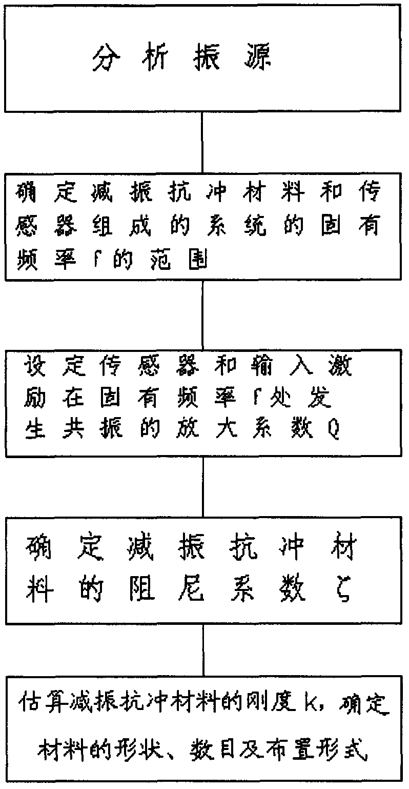
[0030] This embodiment is designed for the vibration reduction and anti-shock method of a certain aerospace sensor, and its flow chart is as follows figure 1 shown. Including analyzing the vibration source; determining the range of the natural frequency f of the system composed of the vibration-absorbing anti-shock material and the sensor; setting the amplification factor Q of the sensor and the input excitation resonating at the natural frequency f of the sensor; determining the damping of the vibration-absorbing and anti-shock material Coefficient ζ; and estimating the stiffness k of the vibration-damping and impact-resistant material through finite element analysis software; determining the shape, number and arrangement of the vibration-damping and impact-resistant material.

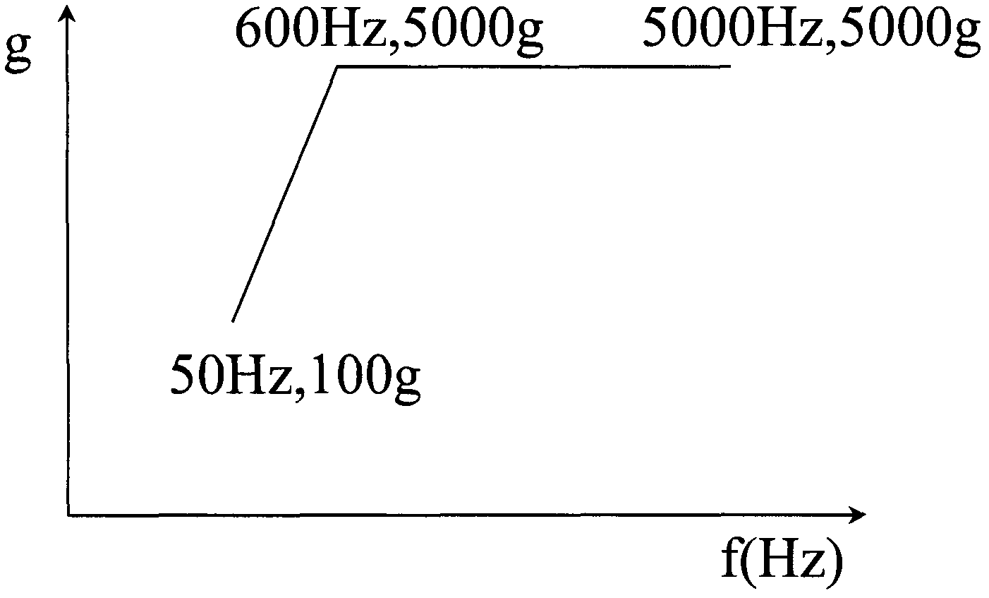
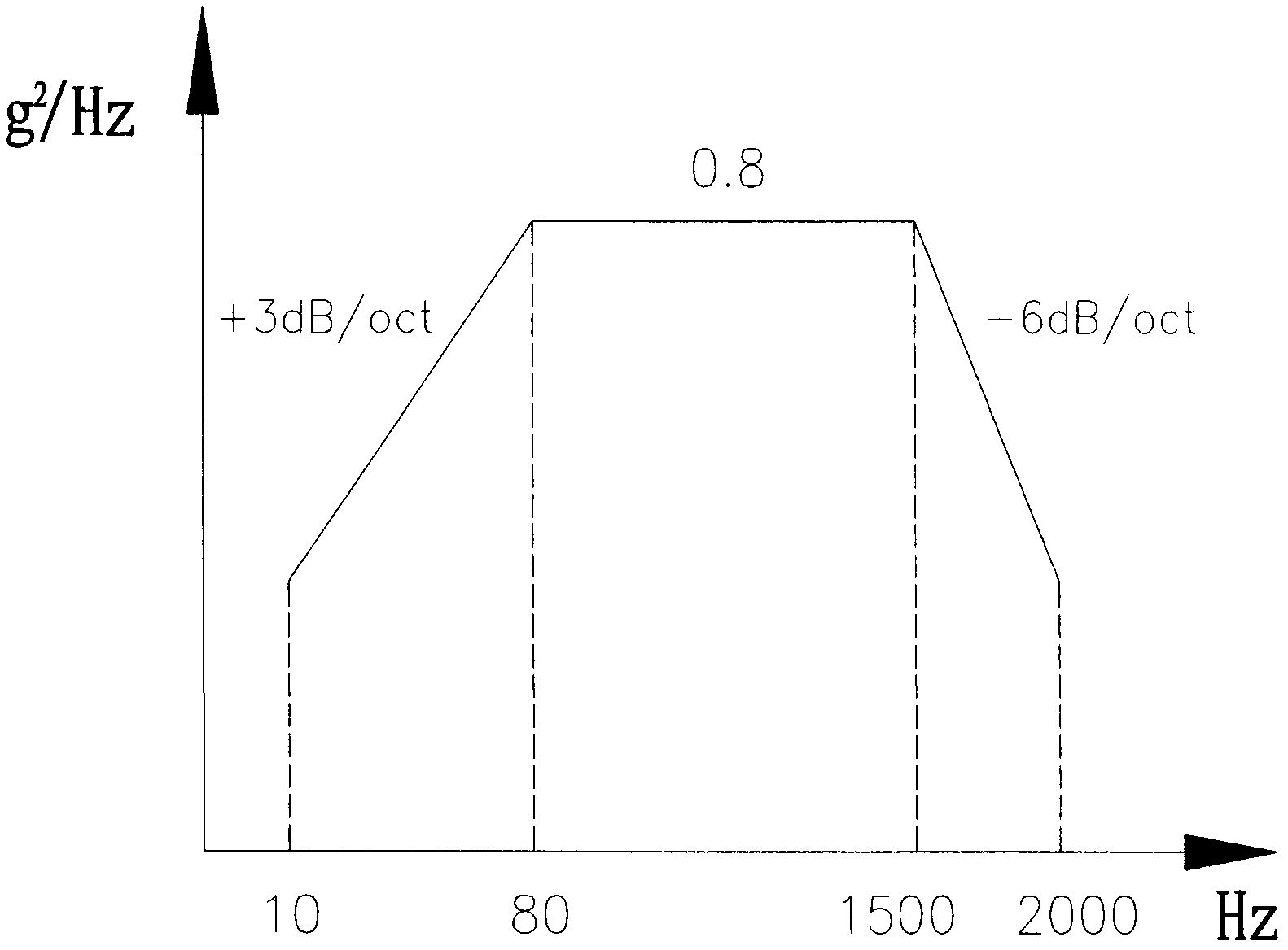
[0031] Such as figure 2 , 3 Shown is the shock test and...


PUM


Abstract

The invention relates to a vibration reduction and impact resistance method for a spaceflight sensor. The vibration reduction and impact resistance method comprises the steps of: analyzing a vibration source; determining the range of the inherent frequency f of a system consisting of vibration reduction and impact resistance materials and a sensor; setting the amplification factor Q for generating resonance of the sensor and the input excitation at the inherent frequency f part of the sensor; determining the damping coefficient Zeta of the vibration reduction and impact resistance materials; estimating the rigidity k of the vibration reduction and impact resistance materials through finite element analysis software, and determining the shape, the number and the arrangement form of the vibration reduction and impact resistance materials; and the like. The vibration reduction and impact resistance method has the advantages that the vibration reduction and impact resistance compatibility of the spaceflight sensor under the mechanical environment is simultaneously considered, firstly, the vibration reduction requirement is met, the proper damping of the vibration reduction and impact resistance materials is selected so that the amplification factor is in a controllable range, next, the inherent frequency of the whole system is reduced to the maximum degree, the transmissibility of the system is reduced for meeting the impact resistance requirement, the vibration reduction and the impact resistance of the spaceflight sensor are effectively realized, and the performance stability of products in spaceflight mechanical environment is ensured.

Description

technical field [0001] The invention belongs to the field of vibration control engineering, and in particular relates to a vibration reduction and shock resistance compatibility method for aerospace sensor products in a mechanical environment. Background technique [0002] As we all know, shock and vibration are harmful in most cases, which will affect the working performance and life of the structure, equipment and the entire system, and will cause product or system function failure or even damage in severe cases. With the development of aerospace vehicles and weapon models, a considerable number of aerospace sensor products are required to withstand harsh mechanical environmental conditions, which puts higher and more stringent requirements on the design work. [0003] The existing design methods of vibration reduction and shock resistance for aerospace sensors do not have a deep understanding of vibration and shock, and it is reflected in the specific design that they can...

Claims


Application Information

Patent Timeline
IPC IPC(8): G01D11/10
Inventor 滕纲刘海涛刘尔静汪守利
Owner BEIJING RES INST OF TELEMETRY
Why Eureka
Try Eureka